91
Indicators Section 4-2
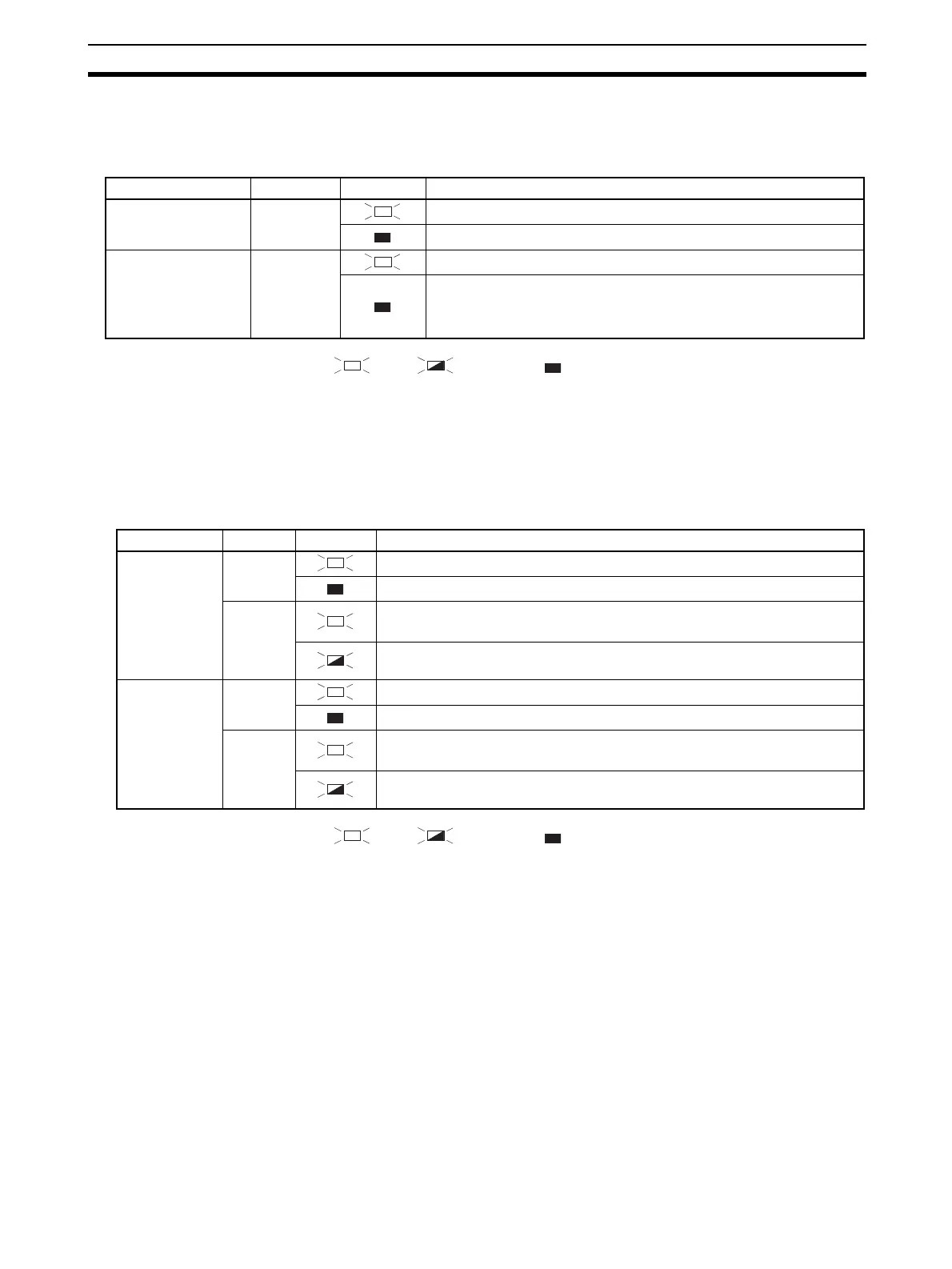
4-2-3 IN PWR/OUT PWR Indicators
The IN PWR and OUT PWR indicators indicate the status of the I/O power
supplied to the DST1-series Safety I/O Terminals.
: Lit : Flashing : Not lit
4-2-4 I/O Indicators
The I/O indicators show the ON/OFF and error status of I/O.
Note The indicators are not lit for safety inputs and safety outputs for which the
Safety Input Channel Mode or Safety Output Channel Mode is set to Not
Used.
: Lit : Flashing : Not lit
Note (1) “n” indicates the terminal number.
(2) Applicable to the DST1-XD0808SL-1 only.
LED Indicators Color Status Meaning
IN PWR Green Normal status of input power
Input power is not supplied.
OUT PWR Green Normal status of output power
Output power is not supplied.
Output power exceeds the upper/lower limit of the power range.
A system error has occurred.
Name Color Status Meaning
IN0 to INn
(See note.)
Yellow Safety input ON.
Safety input OFF.
Red • Error detected in safety input circuits.
• Discrepancy error has occurred set for Dual Channel Mode.
Error detected in the other input circuit set for Dual Channel Mode (no error
in this circuit)
OUT0 to OUTn
(See note.)
Yellow Safety output ON.
Safety output OFF.
Red • Error detected in safety output circuits.
• EDM error (See note 2.)
Error detected in the other output circuit set for Dual Channel Mode (no
error in this circuit)

 Loading...


