41
Maintenance Functions of DST1-series Safety I/O Terminals Section 1-7
1-7-6 Monitoring the Operation Time
Description
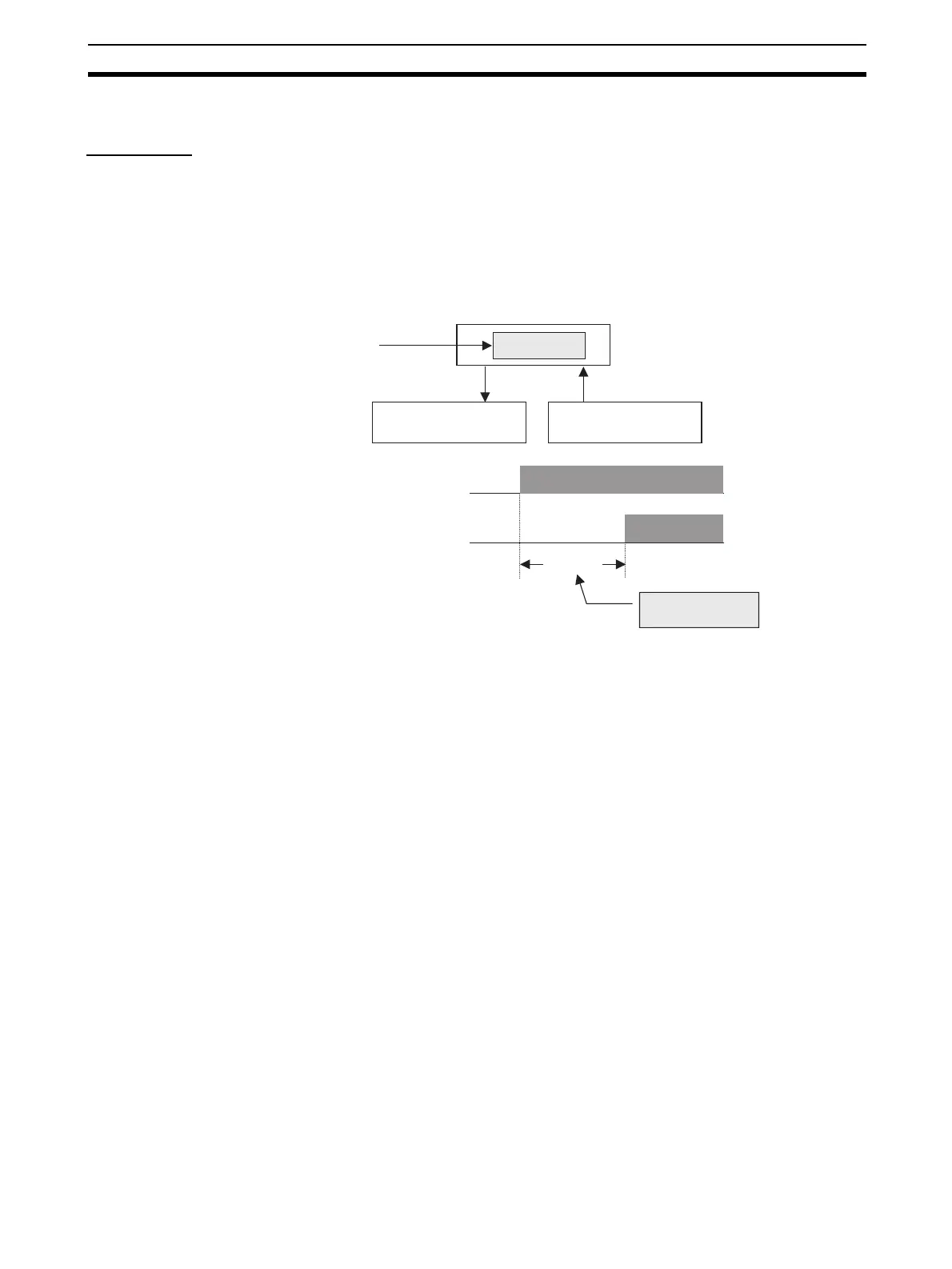
A DST1-series Safety I/O Terminal measures the time from when a safety out-
put turns ON until the safety input turns ON and internally saves the data in
non-volatile memory. If the value of the operation time reaches the threshold
value, the Threshold Response Time Flag in General Status will turn ON.
• Measurement time: 0 to 65,535 ms (stored data: 0000 to FFFF hex)
• Measurement unit: ms
The input reaction time and the output reaction time of the DST1-series
Safety I/O Terminal are added to monitor the operation time.
Maximum input reaction time of the DST1-series Safety I/O Terminal
= 16.2 ms + ON/OFF delay
Maximum output reaction time of the DST1-series Safety I/O Terminal
= 6.2 ms + Relay reaction time (DST1-MRD08SI-1 only)
The measurement is accurate to ±6 ms.
The user can monitor this information using the Network Configurator and
explicit messages.
Measured
time
Operation time
Safety Input B
(Example: Sensor)
Safety Output A
(Example: Contactor)
Safety I/O Terminal
Safety Output A
(Example: Contactor)
Safety Input B
(Example: Sensor)
ON
OFF
ON
OFF
Contactor operation
time
Measured
time

 Loading...


