94
DST1-ID12SL-1 Section 5-1
5-1 DST1-ID12SL-1
5-1-1 Safety Input Specifications
The following table gives the safety input specifications for the DST1-
ID12SL-1.
5-1-2 Test Output Specifications
The following table gives the test output specifications for the DST1-
ID12SL-1.
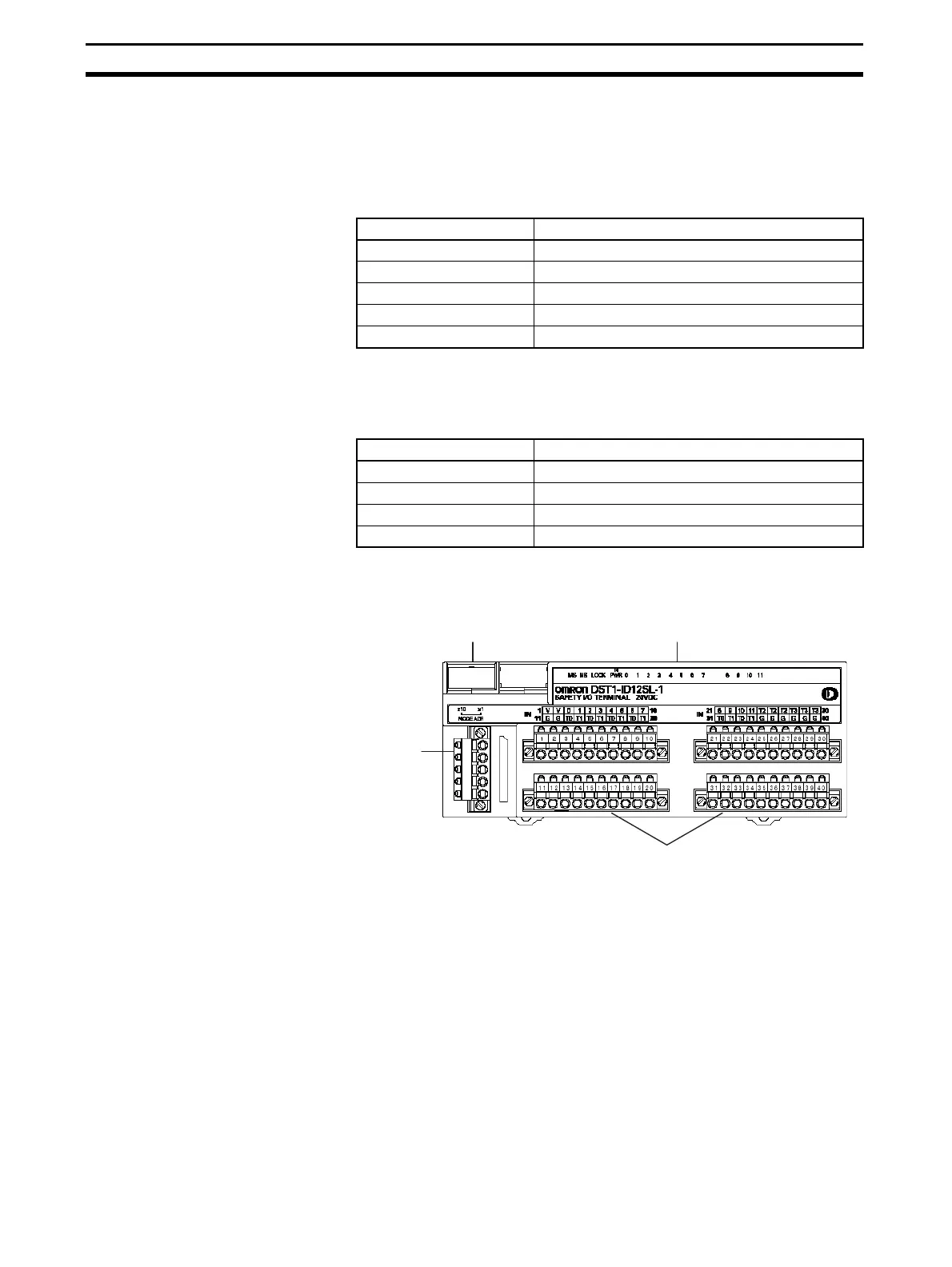
5-1-3 Nomenclature
The following figure shows the names of the parts of the DST1-ID12SL-1.
• Refer to 4-2 Indicators for information on the LED indicators.
• Refer to 2-4 Connecting the Communications Connector for information
on the DeviceNet communications connector.
• Refer to 5-1-4 Internal Circuits and Terminal Arrangement for information
on the terminal blocks.
Item Specifications
Input type Sinking input (PNP)
ON voltage 11 VDC min. between each input terminal and G
OFF voltage 5 VDC max. between each input terminal and G
OFF current 1 mA max.
Input current 6 mA
Item Specifications
Output type Sourcing output (PNP)
Rated output current 0.7 A
Residual voltage 1.2 V max. between each output terminal and V
Leakage current 0.1 mA max.
LED indicators
DeviceNet
communications
connector
Node address switches
Terminal blocks

 Loading...


