51
Connecting the Communications Connector Section 2-4
2-4 Connecting the Communications Connector
Colored stickers are provided on the communications connector that match
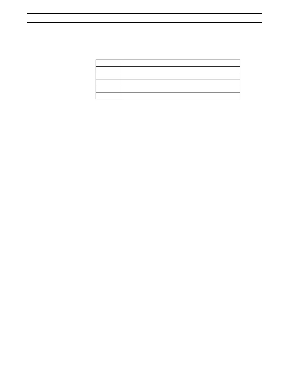
the colors of the lines to be inserted. Check that the colors of the lines and
stickers match when wiring the connectors. The colors are as follows:
Refer to the DeviceNet Operation Manual (Cat. No. W267) for details on com-
munications specifications and wiring.
IMPORTANT • When connecting the communications connector to the DST1, tighten the
screws on the communications connector to 0.25 to 0.3 N⋅m.
•OMRON’s S8@@Power Supplies are recommended for communications
power.
• Be sure to separate communications cables from high-voltage and power
lines.
• Use DeviceNet-compliant Thick Cables or Thin Cables for the communi-
cations cables. Do not use flat cables.
Note • The internal power for the DST1-series Safety I/O Terminals is supplied
from the communications power supply (V+, V−).
Color Signal
Red Power cable positive side (V+)
White High side of communications data (CAN_H)
- Shield
Blue Low side of communications data (CAN_L)
Black Power cable negative side (V−)

 Loading...


