72
Remote I/O Allocations Section 3-2
3-2-3 I/O Data Supported by Each Model
The following tables show the I/O data supported by each model of the DST1-
series Safety I/O Terminals.
Refer to 3-2-4 I/O Assembly Data for data arrangements.
From among the I/O data, safety connections for up to four items, including
one output, can be allocated for the Master Unit and standard connections for
up to two items can be allocated for the Master Unit.
IMPORTANT Communications with up to 15 Safety Controllers for each connection can be
performed using multi-cast connection. If four connections are used, however,
only a maximum of 30 Safety Controllers total can communicate with the
DST1-series Safety I/O Terminals. Up to two safety connections can be used
with the DST1-XD0808SL-1.
DST1-ID12SL-1
The default values for the I/O assembly data are as follows:
Safety connections:
Standard Connections: The default values for each type of connection are
given below.
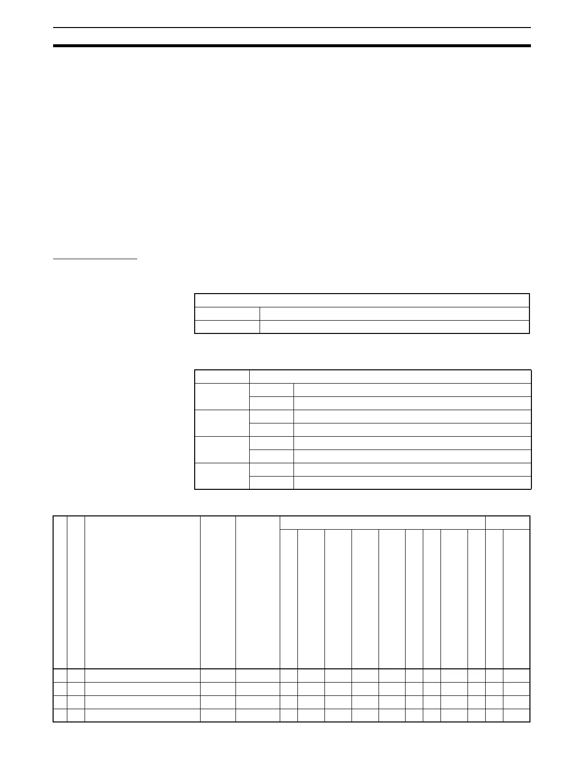
The following I/O data can be selected from the Network Configurator.
Default (Assembly instance number)
IN Safety input assembly 1 (Instance No. 20C)
OUT None
Connection Default (Assembly instance number)
Poll IN Safety input assembly 6 (No. 312)
OUT Standard output assembly (No. 21)
Bit strobe IN Safety input assembly 6 (No. 312)
OUT None
COS IN Test out status with General status assembly (No. 340)
OUT None
Cyclic IN Test out status with General status assembly (No. 340)
OUT None
Safety connection
Standard connection
Network Configurator
setting
Assembly Instance No.
I/O size (bytes)
Inputs Outputs
Safety Input Data
Combined Safety Input Status
Individual Safety Input Status
Combined Safety Output Status
Individual Safety Output Status
Muting Lamp Status
Safety Output Monitors
Individual Test Output Status
General Status
Safety Output Data
Standard Output Data
√√ Safety input assembly 1 20C Input 2 √
√√ Safety input assembly 2 224 Input 2 √√
√√ Safety input assembly 3 22C Input 3 √√
√√ Safety input assembly 4 310 Input 2 √√ √

 Loading...


