18
Logic Functions Section 1-5
1-5-3 Parameters That Can Be Set
Data That Can Be Set for Input Condition Signals
The following data is used for remote I/O data. For details on remote I/O allo-
cations, refer to 3-2-4 I/O Assembly Data.
Example 1: IN0 and IN1 Used in Single Channel Mode
IN0 input condition signal: Bit 0 input condition signal 0 (0/1)
is used.
IN1 input condition signal: Bit 1 input condition signal 1 is used.
Example 2: IN0 and IN1 Used in Dual Channel Mode
IN0 input condition signal: Bit 0 input condition signal 0 (0/1)
is used.
IN1 input condition signal: Not Used.
Data That Can Be Set for Reset Signals
The following data is used for remote I/O data. For details on remote I/O allo-
cation, refer to 3-2-4 I/O Assembly Data.
Example 1: IN0 and IN1 Used in Single Channel Mode
IN0 reset signal: Bit 0 reset signal 0 (0/1) is used.
IN1 reset signal: Bit 1 reset signal 1 is used.
Example 2: IN0 and IN1 Used in Dual Channel Mode
IN0 reset signal: Bit 0 reset signal 0 (0/1) is used.
IN1 reset signal: Setting not required.
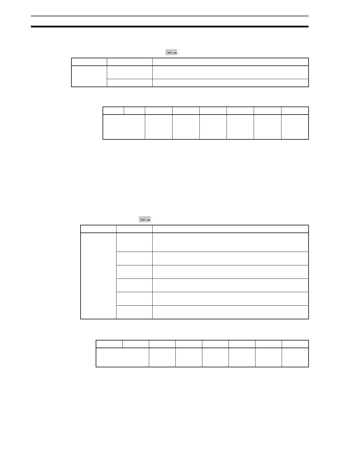
Name Option Setting range
Input condi-
tion signal
Remote I/O Remote safety I/O data (received from Safety Master through the
network)
Input 0 to Input 5 Safety input terminals IN0 to IN5
Bit 7 Bit 6 Bit 5 Bit 4 Bit 3 Bit 2 Bit 1 Bit 0
Reserved for
system.
Input
condition
signal
No. 5
Input
condition
signal
No. 4 (4/5)
Input
condition
signal
No. 3
Input
condition
signal
No. 2 (2/3)
Input
condition
signal
No. 1
Input
condition
signal
No. 0 (0/1)
Name Option Setting range
Reset signal Remote I/O
Low-High-
Low
Remote safety I/O data (received from Safety Master or Standard
Master through the network) used for a Low-high-Low reset.
Remote I/O
Rising Edge
Remote safety I/O data (received from Safety Master or Standard
Master through the network) used for a Rising Edge reset.
IN6 Low-
High-Low
The IN6 terminal is used for a Low-High-Low reset.
IN6 Rising
Edge
The IN6 terminal is used for a Rising Edge reset.
IN7 Low-
High-Low
The IN7 terminal is used for a Low-High-Low reset.
IN7 Rising
Edge
The IN7 terminal is used for a Rising Edge reset.
Bit 7 Bit 6 Bit 5 Bit 4 Bit 3 Bit 2 Bit 1 Bit 0
Reserved for system. Reset sig-
nal
No.5
Reset sig-
nal
No.4 (4/5)
Reset sig-
nal
No.3
Reset sig-
nal
No.2 (2/3)
Reset sig-
nal
No.1
Reset sig-
nal
No.0 (0/1)

 Loading...


