124
Wiring and Configuration Section 8-1
8-1 Wiring and Configuration
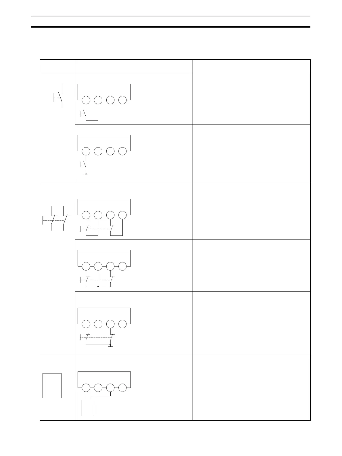
The following table shows input device connection methods and configuration.
Connected
device
Schematic diagram Configuration
Reset switch Connect the switch between IN0 and T0. Safety Input used as “Single Channel input” with-
out test output.
Test output used as power supply output.
Connect the switch between 24 V DC and IN0. Safety Input used as “Single Channel input” with-
out test output.
Emergency
stop switch
Door monitor
Connect the switches between IN0 and T0, and
IN1 and T1.
Safety Inputs used as “Dual Channel input” with
test output.
Test outputs used as “Pulse Test Output”.
Connect the switches between T0 and IN0, IN1. Safety Inputs used as “Dual Channel input” with
test output.
Test output used as “Pulse Test Output”.
Connect the switches between 24 V DC and IN0,
IN1.
Safety Inputs used as “Dual Channel input” with-
out test output.
Safety
Light Curtain
Connect OSSD1 and OSSD2 to IN0 and IN1,
respectively.
Safety Inputs used as “Dual Channel input” with-
out test output.
IN0 T0 IN1 T1
IN0 T0 IN1 T1
24 V
IN0 T0 IN1 T1
IN0 T0 IN1 T1
IN0 T0 IN1 T1
24 V
OSSD2
OSSD1
OSSD2
OSSD1
IN0
T0
IN1
T1

 Loading...


