52
Node Address Section 2-5
2-5 Node Address
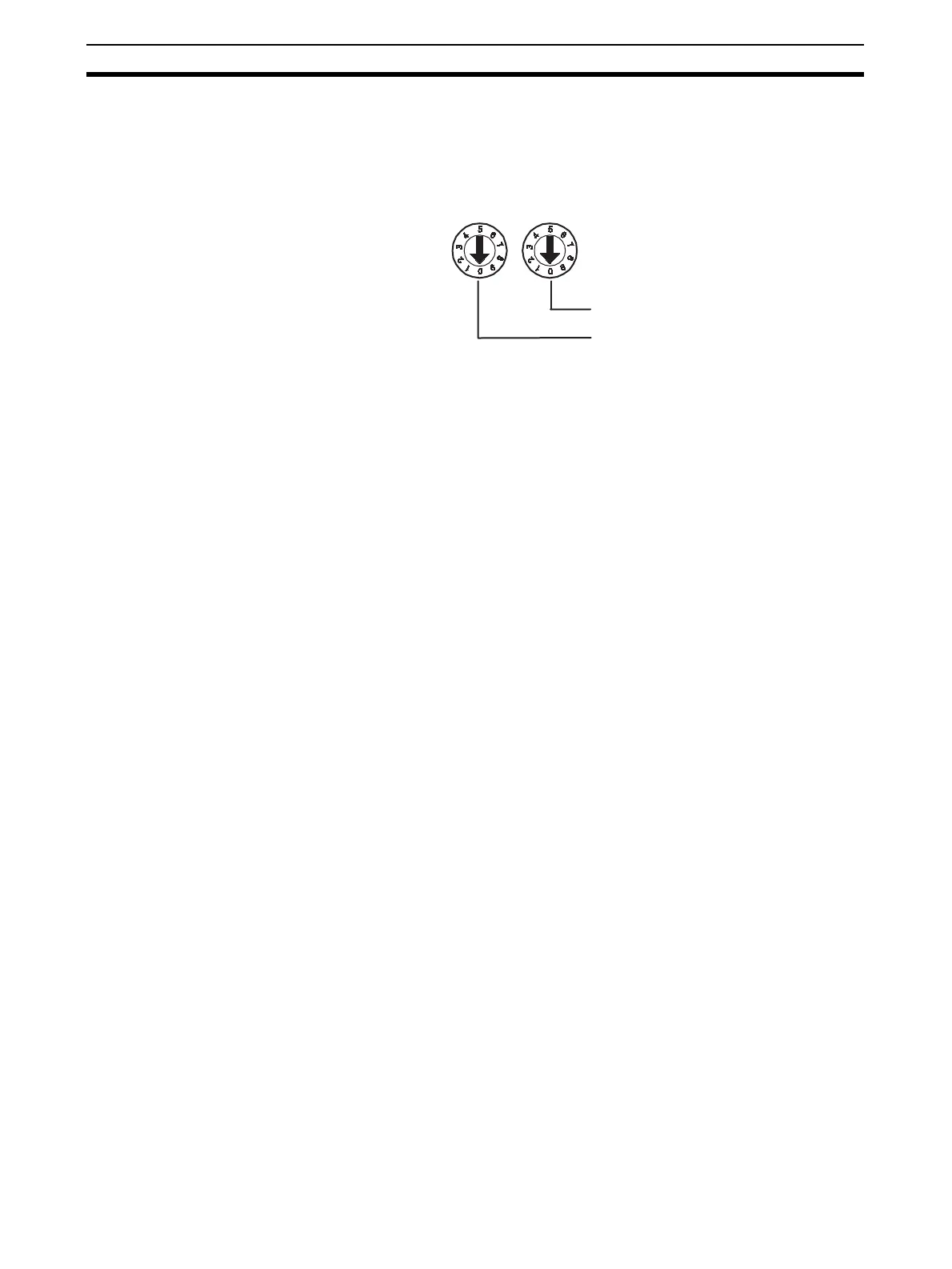
Set the node address using the two rotary switches on the front panel of the
DST1-series Safety I/O Terminals. The default setting is 63. Set the tens digit
of the node address (decimal) using the left rotary switch and set the ones
digit using the right rotary switch. A value between 00 and 63 can be set.
If a node address between 64 and 99 is set, the node address can be set from
the Network Configurator.
IMPORTANT • The node address must be set while the communications power supply is
turned OFF.
• Do not change the rotary switches while the power is ON. The DST1-
series Safety I/O Terminals will detect this as a change in the configura-
tion and will switch to fault state.
• Use a small flat-blade screwdriver to set the rotary switches, being careful
not to scratch them.
2-6 Configuration
Configure the DST1-series Safety I/O Terminals using the Network Configura-
tor. Refer to Section 3 Configuration for details on settings. Refer to the Sys-
tem Configuration Manual (Cat. No. Z905) for Network Configurator operating
procedures.
Ones digit of node address
Tens di
it of node address

 Loading...


