27
Maintenance Functions of DST1-series Safety I/O Terminals Section 1-7
1-7 Maintenance Functions of DST1-series Safety I/O
Terminals
DST1-series Safety I/O Terminals support the same maintenance functions
as DRT2-series Smart Slaves, which are Standard Slaves.
1-7-1 Network Power Supply Voltage Monitor
Description
DST1-series Safety I/O Terminals always monitor the present, minimum, and
maximum values of the network power supply voltage. If the voltage falls
below the set threshold voltage (11 V in the default settings), the Threshold
Network Power Voltage Error Flag will be turned ON in the General Status.
The user can monitor this information using the Network Configurator and
explicit messages.
Note • The minimum communications power voltage of the DeviceNet net-
work is 11 V. If the voltage falls below 11 V, the Configurator may not
be able to read measured values.
• The present, maximum, and minimum values of the network power
supply voltage are cleared when the power supply to the DST1-
series Safety I/O Terminal (network power) is turned OFF.
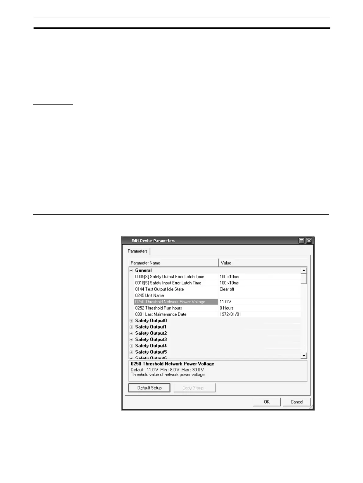
Setting the Threshold Network Power Supply Voltage Using the Network Configurator
Set the threshold voltage in the Threshold Network Power Voltage Field in the
General Parameter Group.

 Loading...


