4.10
9850045 R01 - 2020-2021 RANGER 1000 Service Manual
© Copyright Polaris Inc.
CRANKSHAFT POSITION SENSOR (CPS)
CPS OPERATION OVERVIEW
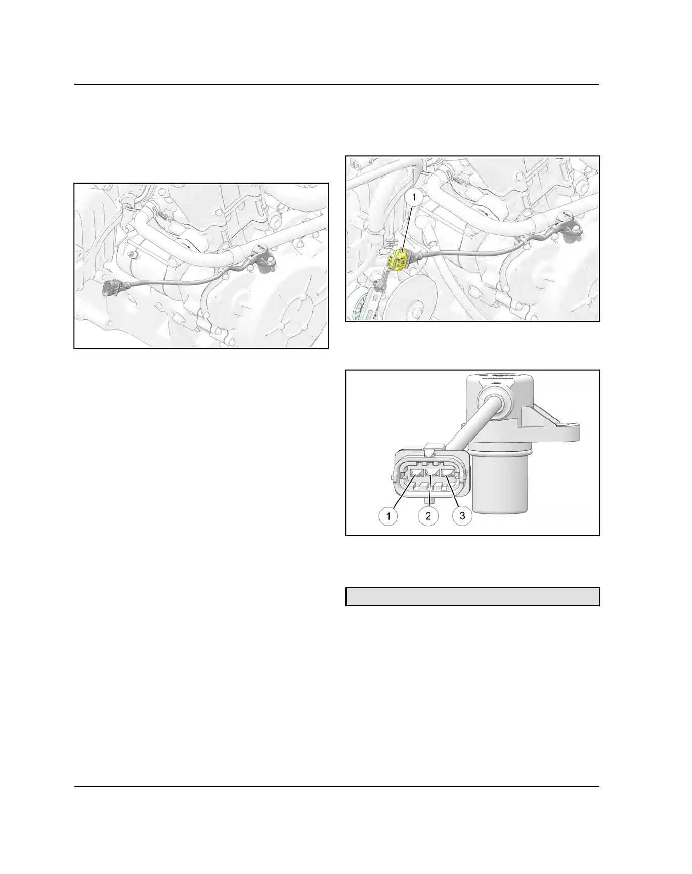
Mounted on top of the stator cover, the crankshaft
position sensor is essential to engine operation,
constantly monitoring the rotational speed (RPM) and
position of the crankshaft.
A ferromagnetic 35-tooth encoder ring with a missing
tooth is built onto the flywheel. Refer to Camshaft Timing
- Quick Reference page for further details.
The inductive speed sensor is mounted 1.0 ± 0.26 mm
(0.039 ± 0.010 in.) away from the encoder ring. During
rotation, an AC pulse is created within the sensor for
each passing tooth. The ECU calculates engine speed
from the time interval between the consecutive pulses.
The encoder ring missing tooth creates an “interrupt”
input signal, corresponding to specific crankshaft
position. This signal serves as a reference for the control
of ignition timing by the ECU. Synchronization of the
CPS and crankshaft position takes place during the first
two revolutions each time the engine is started. This
sensor must be properly connected at all times. If the
sensor fails or becomes disconnected for any reason, the
engine will stop running.
CPS TEST
The CPS is a sealed, non-serviceable assembly. If fault
code diagnosis indicates a problem with this sensor, test
as follows:
1. Locate the CPS harness connector
q
above the shift
cable on the right side of the vehicle and disconnect
the harness.
2. Pin
q
is for the shield circuit and it should be OL to
pins
w
&
e
. A resistance reading would indicate a
shorted sensor.
3. Connect an ohmmeter between CPS pin terminals
w
&
e
. A resistance value of 1000Ω ± 10% at room
temperature should be obtained.
CPS Resistance Specification:1000 Ω ± 10%
4. If the resistance is correct:
• Test the main harness circuit between the sensor
connector terminals and the corresponding pin
terminals at the ECU (see wiring diagram).
• Check the sensor mounting, air gap, flywheel encoder
ring for damage or runout, and flywheel key. Inspect
CPS and flywheel encoder ring for damage. Refer to
CPS REPLACEMENT procedure.
5. If the resistance is incorrect, follow the CPS
REPLACEMENT procedure.
ENGINE ELECTRICAL
 Loading...