EasyManuals Logo
Home>Polaris>Offroad Vehicle>TRAIL BOSS 2003

Polaris TRAIL BOSS 2003 User Manual

Polaris TRAIL BOSS 2003
213 pages
To Next Page IconTo Next Page
To Previous Page IconTo Previous Page
Page #192 background imageLoading...
Page #192 background image
ELECTRICAL
10.9
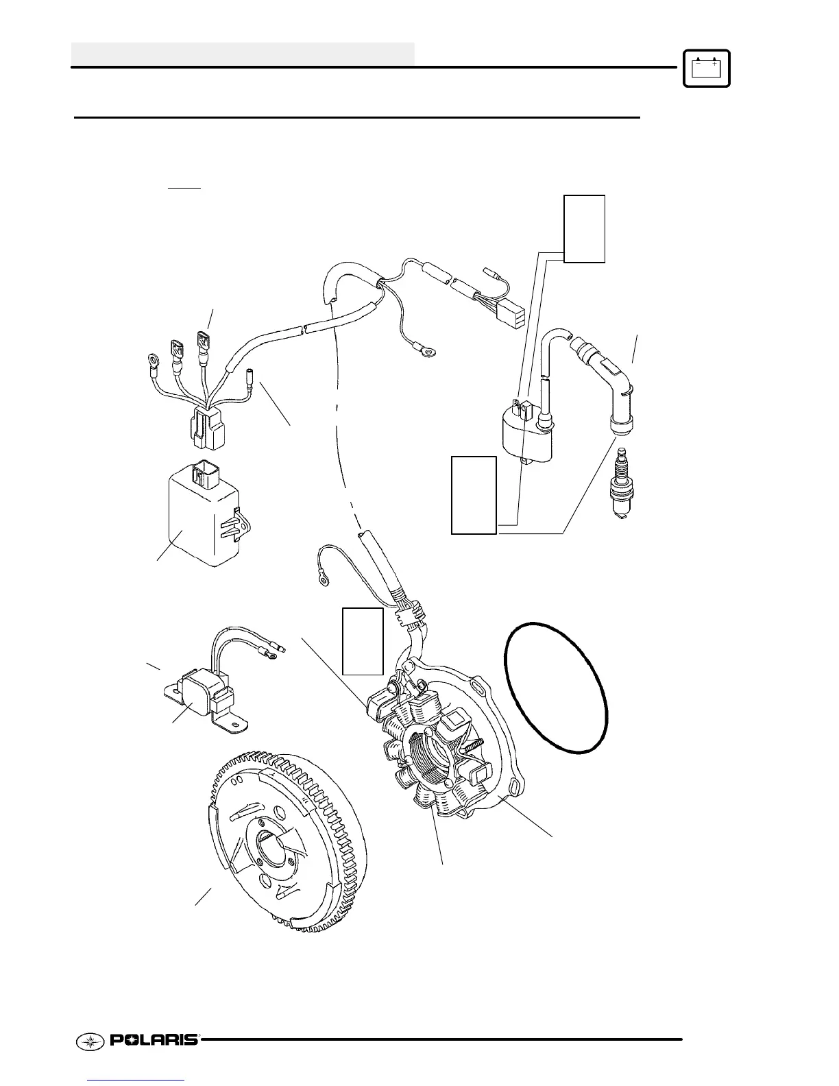
COMPONENTS OF ES32PF / 200 WATT ALTERNATOR
battery charge Coils
Flywheel and
Ring Gear Casting.
Refer to Page 10.8 for
identification.
Resistor
Cap
CDI Box
Stator Plate
Pulse Coil (Trigger)
Air Gap: .016-.030²
(.4-.75mm)
Meter
W
Ignition Coil
Primary
Winding
.3 W
Ignition Kill
Wire
(Black)
Coil Lead
Secondary Coil
Check coil mount to verify
ground to engine (0-.2 )W
Refer To Wiring Diagrams For
Specified Stator Coil Resistance
Magnetic
Switch
Meter
10.5KW
W
Note: DC /CDI compone nts ar e not compa tible with any othe r type of ignition
12 Volt DC
Supply Wire
(Red)
520W
W
Meter

Table of Contents

Questions and Answers:

Question and Answer IconNeed help?

Do you have a question about the Polaris TRAIL BOSS 2003 and is the answer not in the manual?

Polaris TRAIL BOSS 2003 Specifications

General IconGeneral
BrandPolaris
ModelTRAIL BOSS 2003
CategoryOffroad Vehicle
LanguageEnglish

Related product manuals