ELECTRICAL
10.19
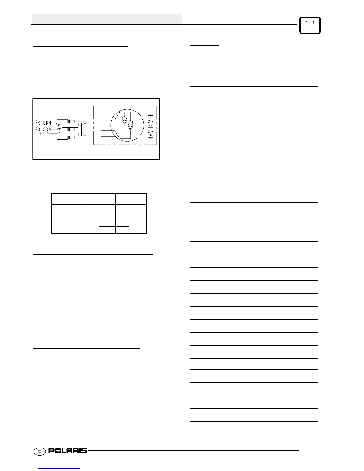
HEADLAMP SWITCH
Follow procedure, Headlight Lamp Replacement, on
Page 10.17--10.18 to access connector . Probe the
headlamp plug wires (Brown, Green, Yellow) at back
of connector . Turn headlight on. Test for battery
voltage across the connections.
Check continuity across pins of the left handle bar
switch assembly. See illustration below.
Continuity
R/W
Grn
Off
On
F
F
NEUTRAL LIGHT CIRCUIT
OPERA
TION
Power is supplied to the transmission switch from the
Red/White wire when the key and engine stop switch
are on. When neutral is selected, power flows through
the switch to the Green/White wire, through the lamp
and to ground via the Brown wire.
If the light is not on when neutral is selected, check the
bulb. If the bulb is good, check the wiring,
transmission switches, and lamp socket ground path.
BRAKE LIGHT SWITCH
1. Remove front cover.
2. Disconnect wire harness from switch.
3. Connect an ohmmeter across switch contacts.
Reading should be infinite (∞).
4. Apply brake at handlebar lever and check for
continuity between switch contacts. Replace
switch if there is no continuity or greater than .5
ohms resistance when the brake is applied with
slight pressure.
NOTES
 Loading...