78 Rockwell Automation Publication 750-AT006D-EN-P - January 2022
Chapter 5 Manual Tuning
3. Run the drive (command motion) and slowly increase 10:1956 [u VReg Kp] while looking for a reduction in velocity error.
a. If the 10:901 [Load Ratio] = 0 and 10:2020 [LdObs Mode] = LdObs VelEst (2) or Vel Est Only (3), set
10:2022 [u LdObs Kp] = 4 * 10:1956 [u VReg Kp].
If 10:2020 [LdObs Mode] = Disabled (0), there is no need to adjust 10:2022 [u LdObs Kp].
b. Otherwise, set 10:2022 [u LdObs Kp] = 1 * 10:1956 [u VReg Kp].
c. Continue to increase 10:1956 [u VReg Kp] and 10:2022 [u LdObs Kp] until ringing occurs in torque signals or an audible noise exists
at any time while tuning.
d. Stop and restart motion after each modification of 10:1956 [u VReg Kp] and 10:2022 [u LdObs Kp].
4. Manually compensate for resonances.
a. Set 10:2110 [AdptTune Con-fig] = Disabled (0) to manually tune the torque low pass and notch filters. Even when Adaptive Tuning is
disabled, it continues to identify resonances and displays the frequency, magnitude, and width in 10:2123 [TrqNF Freq Est],
10:2124 [TrqNF Mag Est], and 10:2125 [Trq NF Wdth Est] respectively.
b. Enable and jog the drive (momentarily command motion) to listen for audible resonance. Jogging the drive is unnecessary if
audible resonance is heard while enabling the drive. If an audible high frequency resonance is not present, skip the remaining
steps for manual compensation of resonances.
c. Identify the resonant frequency.
Method 1
: Monitor parameter 10:2123 [Trq NF Freq Est]. If a high frequency resonance is present, this parameter displays the largest
magnitude frequency identified in Hz. If this parameter displays a value of 0, then a high frequency resonance is not present. It
may be necessary to adjust parameter 10:2112 [Trq NF Freq LLim] to be able to see a resonant frequency. See Adaptive Tuning
on
page 34 for more information on how to configure Adaptive Tuning.
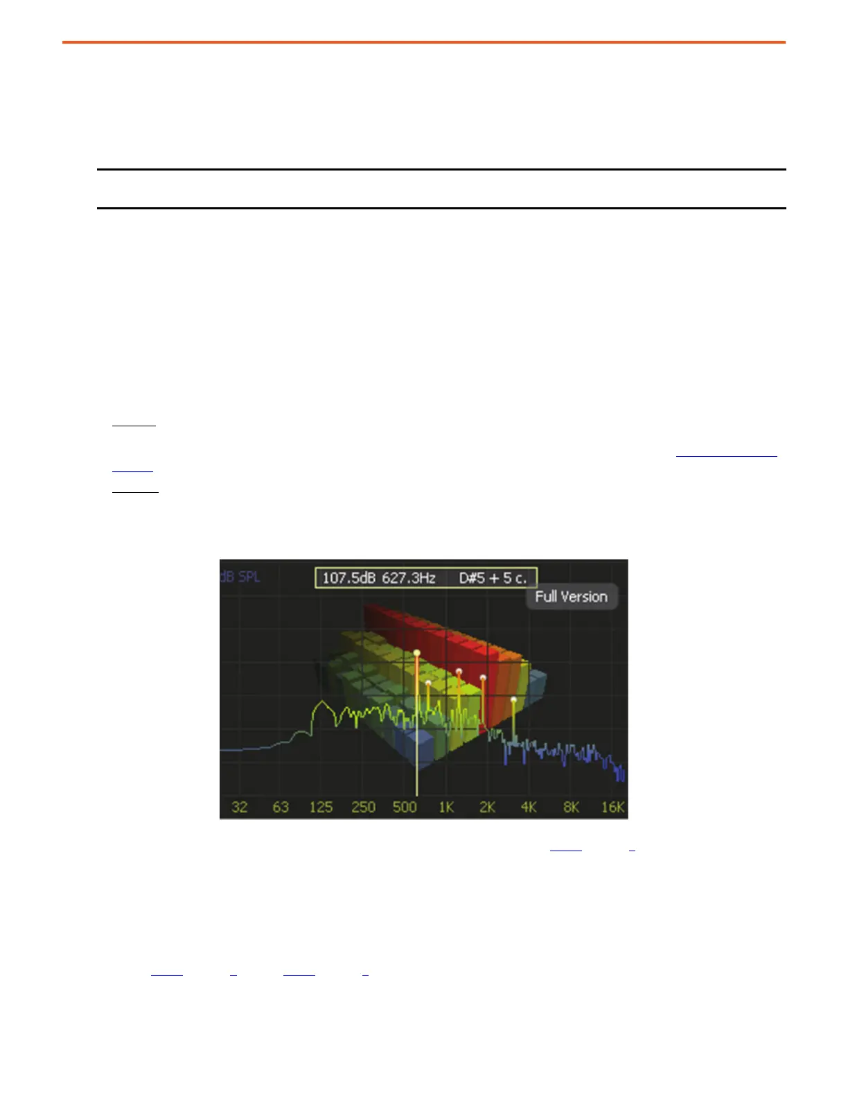
Method 2
: Use an FFT mobile application to identify resonances. An iAnalyzer Lite example shows that the dominant resonance
frequency has the largest peak. Select the frequency with the largest magnitude. If multiple resonances have nearly the same
magnitude, then select the lowest frequency with that magnitude.
Figure 70 - iAnalyzer Lite Example
d. If identified resonances are below the torque loop bandwidth or a low pitch growling sound is present, then instability is present
and you must decrease 10:1956 [u VReg Kp] and 10:2022 [u LdObs Kp], then return to step 4
substep c to identify a resonance.
e. Set the torque notch filter 1 parameters to the values that follow:
10:2159 [Trq NF1 Freq] = set to the identified resonant frequency
10:2161 [Trq NF1 Width] = 0.707
10:2163 [Trq NF1 Depth] = 0
10:2165 [Trq NF1 Gain] = 1
f. Repeat step 4
substep b through step 4 substep e to identify a new resonance and set torque notch filter 2 parameters similarly.
Repeat the process to set torque notch filter 3 and 4 parameters or until an audible high frequency resonance is not present.
g. If all four notch filters are configured and audible resonances are still present, adjust 10:2155 [u Trq LPF BW] and/or reduce 10:1956
[u Vreg Kp] and 10:2022 [u LdObs Kp] until the resonances vanish.
IMPORTANT Every time that you increase or decrease 10:1956 [u VReg Kp] in the following steps, also increase or decrease
10:2022 [u LdObs Kp] to keep the 1 or 4 times ratio between them constant.
 Loading...


