Rockwell Automation Publication 750-AT006D-EN-P - January 2022 95
Chapter 6 Active Front End Tuning
Figure 77 - Flow Diagram for Ride Through
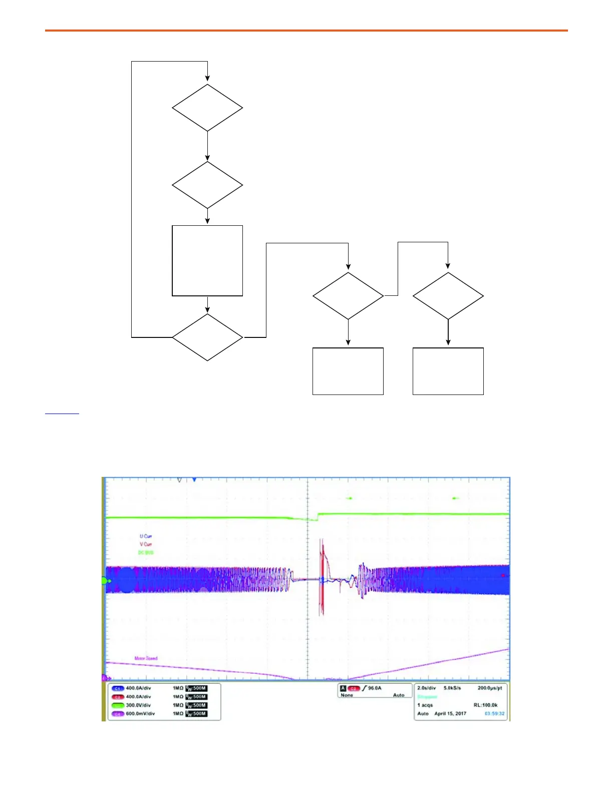
Figure 77
is a set of oscilloscope traces from an actual test. In this test, we induced a power loss condition. We have set
13:181 [PLL LOS Det Actn] to 0 Ride Thru, 13:170 [PwrLoss Det Actn] and 13:173 [VltgSag Det Actn] to 2 Ride Thru in the line-side converter. We
set 10:116 [Bus Reg Mode A] to 1 Adjust Freq, 10:270 [Pwr Loss Actn] to 1 Alarm, 10:271 [Pwr Loss Mode A] to 1 Decel, 10:272 [Pwr Loss A Level]
to 50V, and 10:273 [Pwr Loss A Time] to 60 s in the motor-side inverter. The duration of the power loss in this test was approximately 10 s.
Figure 78 - Ride Through for PowerFlex 755TR Drives
Power Disturbance?
Disturbance Acon =
Ride Thru?
Ride Thru Timer
Expired?
Ride Thru Expired
Acon = Alarm?
Yes
Yes
Yes
Yes
No
No
Disable PWM, Reset
Current Loop
Integrator, Reset
Voltage Loop
Integrator
Alarm
Ride Thru Expired
Acon = Fault?
Fault
 Loading...


