Rockwell Automation Publication 750-AT006D-EN-P - January 2022 99
Chapter 6 Active Front End Tuning
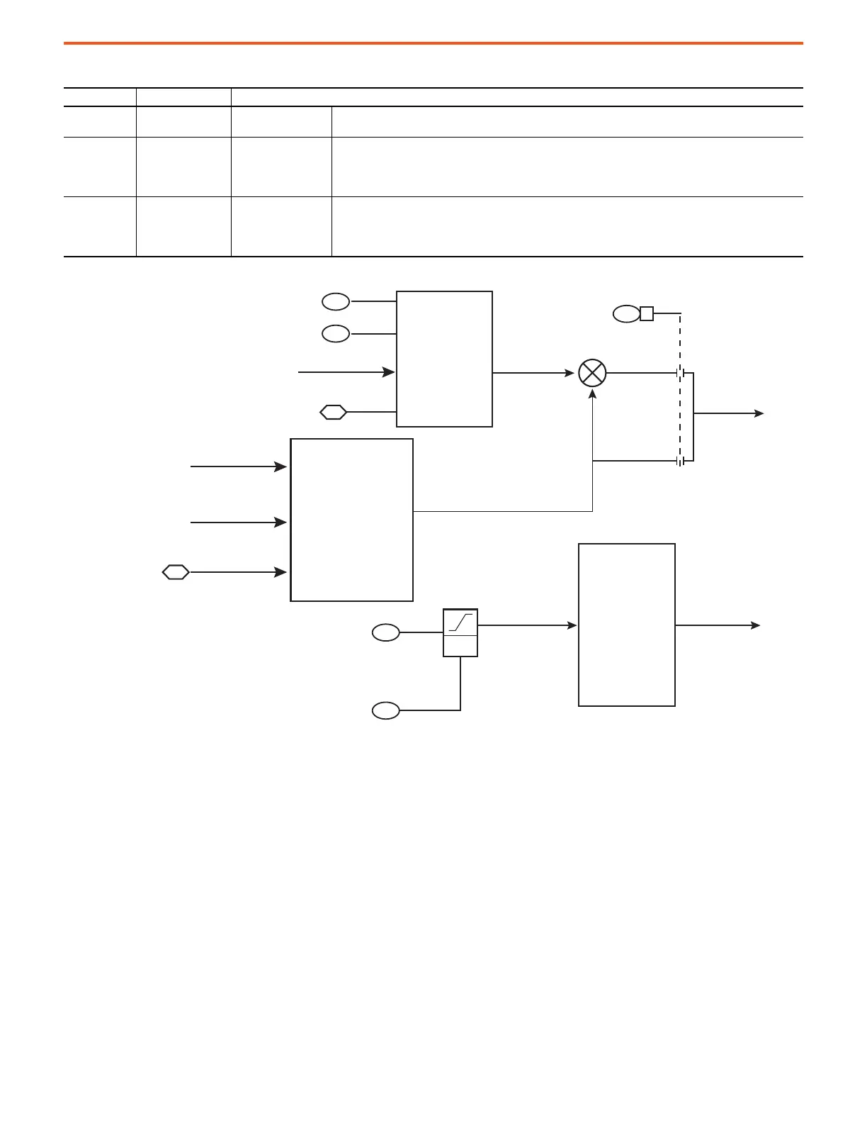
Figure 81 - Function Block Diagram of the Reactive Power Control with Configuration Parameters Shown
13:73 [Reactv Cur Cmd]
Reactive Current
Command
Displays the commanded Reactive Current reference.
13:82 [BusAutoAdjReg Kp]
VAR Control Bus Auto
Adjust Regulator Kp
Enter the value for the proportional gain of the DC Bus Automatic Adjustment Regulator.
• This feature is active only when 13:45 [DC Bus Reference Sel] is set to VAR Control (3).
• It automatically raises the DC bus level to improve the efficiency of transfer of reactive power to the AC
line.
13:83 [BusAutoAdjReg Ki]
VAR Control Bus Auto
Adjust Regulator Ki
Enter the value for the integral gain of the DC Bus Automatic Adjustment Regulator.
• This feature is active only when13:45 [DC Bus Reference Sel] is set to VAR Control (3).
• It automatically raises the DC bus level to improve the efficiency of transfer of reactive power to the AC
line.
Table 35 - Reactive Power Control Function Parameter Settings (Continued)
Parameter No. Parameter Name Description
82
83
3
67
40
0
1
+
+
69
70
Rate
Limit
kVAR Ref
kVAR Rate Limit
CurrPwrLmt [F5]
Reference Reacve
Current Calculaon
Acve Cur Cmd
SourceImpedance
LscData [C5]
BusRefAutoAdjCalculaon
VoltRefGen [C5]
BusRefAutoAdjReg
VarDCBAdJDIs
3
Vq
Metering [D1]
Vq
Metering [D1]
BusAutoAdjReg Kp
BusAutoAdjReg KI
Port 0, DC Bus Volts
Metering [D5]
 Loading...


