98 Rockwell Automation Publication 750-AT006D-EN-P - January 2022
Chapter 6 Active Front End Tuning
internal regulator can turned on and off using 13:40 [Conv Options Config] Bit 3 Cfg:VarDCBAdjDis and fine tuned, if needed, using 13:82
[BusAutoAdjReg Kp] and 13:83 [BusAutoAdjReg Ki]. Table 35 summarizes the reactive power control parameters. Figure 81 shows a simplified
block diagram of this function.
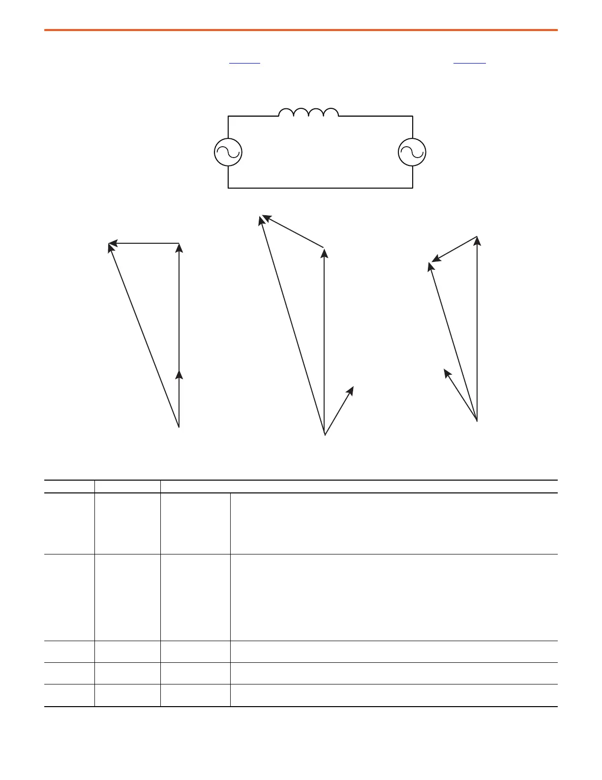
Figure 79 - Simplified Equivalent Circuit of Power Converter Connected to Grid Source
Figure 80 - Phasor Diagram of the Converter Current
Table 35 - Reactive Power Control Function Parameter Settings
Parameter No. Parameter Name Description
13:40 [Conv Options Cfg]
Converter Options
Configuration
Bit 3 VarDCBAdjDis disables the Var control DC bus automatic adjustment feature.
• This feature is active only when 13:45 [DC Bus Reference Sel] is set to VAR Control (3).
• It automatically raises the DC bus level to allow for Var control.
Bit 7 VAR OnlyMode enables the line-side converter to produce reactive power only.
• In this mode, the whole rating of the power structure is dedicated for reactive power compensation.
• The converter does not provide any active power to loads connected to the DC bus.
13:69 [kVAR Ref]
Reactive Power
Reference
Enter a value to set the Reactive Power (kVAR) reference.
• Negative values command a leading power factor (injecting reactive power to the line) and positive values
command a lagging power factor (consuming reactive power from the line).
• When the value is zero, the line-side converter will regulate reactive current to maintain a unity power
factor.
• If the line-side converter is not in Reactive Power Only mode
(13:40 [Conv Options Config] Bit 7 Cfg:VAR OnlyMode is cleared), the line-side converter prioritizes the
active power needs of the loads connected to the DC bus.
– The line-side converter dedicates its remaining capacity to reactive power.
13:70 [kVAR Rate Limit]
Reactive Power Rate
Limit
Enter a value to set the maximum rate of change for the Reactive Power when the Reactive Power reference
is non-zero.
13:71 [kVAR Available]
Reactive Power
Available
Displays available Reactive Power based on the rating and the load of the line-side converter.
13:72 [kVAR Command]
Reactive Power
Command
Displays the limited and conditioned Reactive Power reference.
• The Reactive Power regulator consumes this signal as its command.
V
conv
V
grid
L
V
conv
I
conv
X
V
grid
I
conv
V
conv
V
grid
I
conv
I
conv
X
V
conv
V
grid
I
conv
I
conv
X
at Unity Power Factor Injecting Reactive Power to the Grid (Lag) Absorbing Reactive Power from the Grid (Lead)
 Loading...


