4 Checking and Performing Printer Adjustments
36
CL4NX/CL6NX Service Manual
4.1
Checking the Direct Current Power Voltage
This procedure enables checking various direct current voltages of the main (CONT) PCB board.
Required tools:
• Digital multimeter
• Phillips screwdriver (JIS #2 or equivalent)
1 Make sure that the printer is in power off mode, then disconnect the power cord from
the AC outlet.
2 Remove the left housing cover from the printer.
Refer to Section 5.1.1 Remove the Left Housing Cover for details.
3 Set the digital multimeter to direct current, voltage mode.
4 Connect the power cord to an AC outlet.
5 Press the power button on the operator panel for more than one second to power on
the printer.
6 Touch the negative measurement probe to the [GND] point of the main (CONT) PCB.
And then touch the positive probe to the test point [TP] as indicated below.
Refer to the Figure 4.1 for the position of the test points.
• Touch the positive probe to the [5VC] point and measure the voltage of +5.0 V.
• Touch the positive probe to the [TP5], [TP7], or [TP26] points and measure the voltage of +3.3 V.
• Touch the positive probe to the [TP16], [TP50] (for CL4NX printer) or [1.8V] (for CL6NX printer) point
and measure the voltage of +1.8 V.
Note: For CL6NX printer, the FPGA PCB assembly blocks the [TP50] point. Use the [1.8V] test point to
measure the voltage of +1.8 V.
• Touch the positive probe to the [TP13] or [TP47] points and measure the voltage of +1.26 V (MPU).
• Touch the positive probe to the [TP12] or [TP46] points and measure the voltage of +1.1 V (CORE).
Criteria
7
Replace the main (CONT) PCB if the supply voltage of +5.0 V/ +3.3 V/ +1.8 V/ +1.26 V
/ 1.1 V does not meet the criteria.
Refer to Section 5.5 Replacing the Main (CONT) PCB for details.
8 Power off the printer.
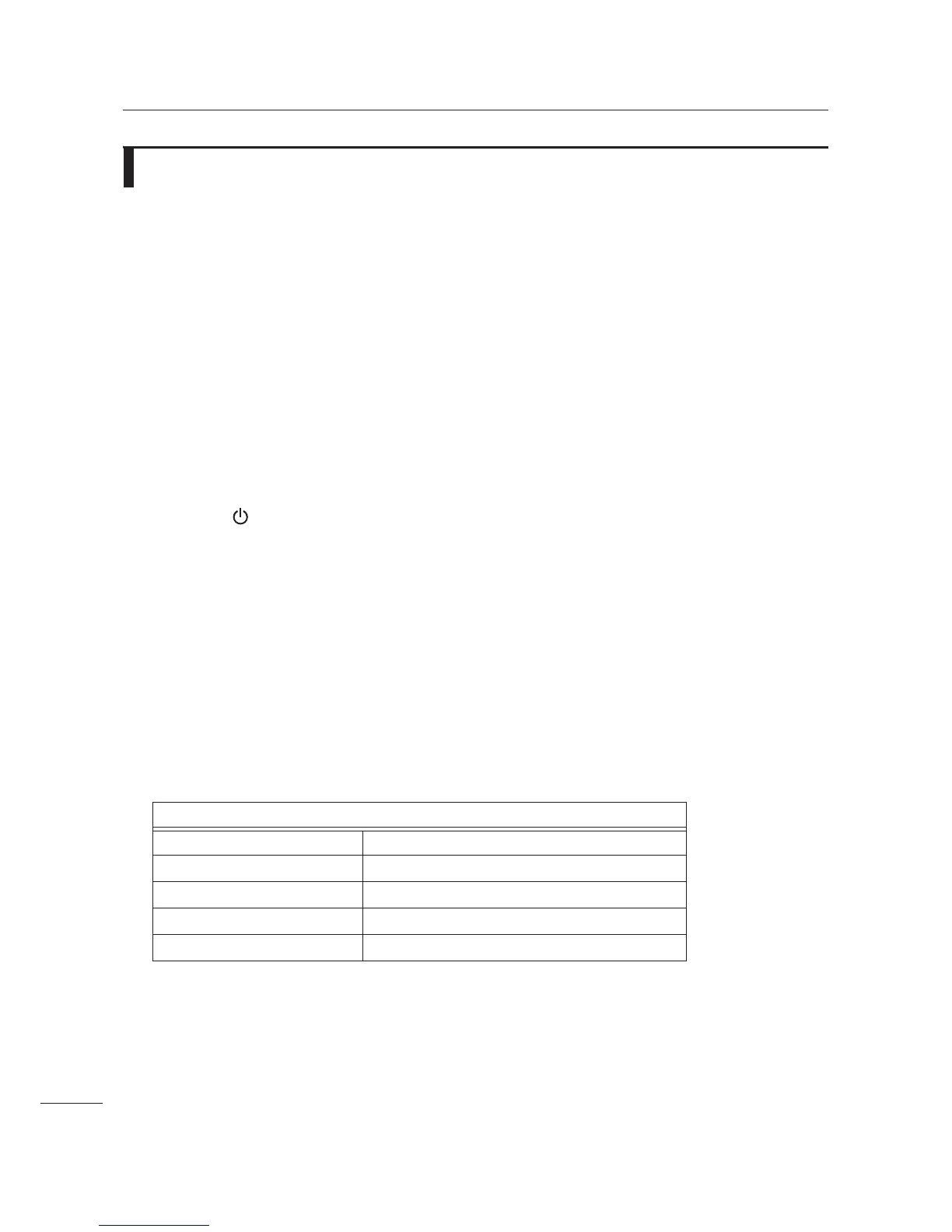
Table of Normal Performance Values:
+5.0 V +4.8 V to +5.2 V
+ 3.3 V +3.2 V to +3.4 V
+1.8 V +1.7 V to +1.9 V
+1.26 V +1.21 V to +1.326 V
+1.1 V +1.056 V to +1.144 V
 Loading...