5 Replacement
85
CL4NX/CL6NX Service Manual
5.9
Replacing the FPGA PCB (CL6NX Only)
Required tool:
• Phillips screwdriver (JIS #2 or equivalent)
1 Make sure that the printer is in power off mode, then disconnect the power cord from
the AC outlet.
2 Remove the left housing cover.
Refer to Section 5.1.1 Remove the Left Housing Cover.
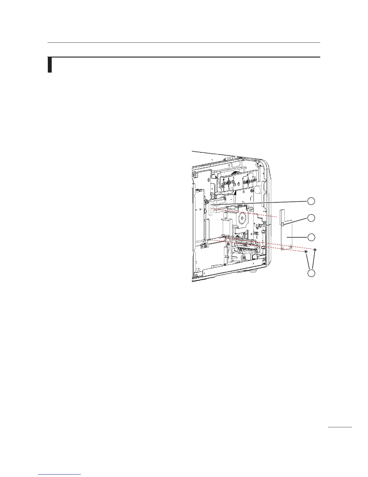
3 Disconnect the CN1 connector . on the
FPGA PCB
3.
4 Remove two screws $ attaching the
FPGA PCB
3 to the bracket.
5 Remove the FPGA PCB 3 from the
FPGA connector
/ on the main
(CONT) PCB.
6 Replace the defective FPGA PCB 3
with a new FPGA PCB 3.
7 Perform the assembly with the reverse
procedure.
 Loading...