5 Replacement
78
CL4NX/CL6NX Service Manual
5.5
Replacing the Main (CONT) PCB
Required tool:
• Phillips screwdriver (JIS #2 or equivalent)
1 Make sure that the printer is in power off
mode, then disconnect the power cord
from the AC outlet.
2 Remove the left housing cover.
Refer to Section 5.1.1 Remove the Left Housing Cover.
Refer to Section 5.8 Replacing the Interface Board to remove the interface board if applicable.
3 Disconnect all the cables from the
connectors (as listed below) on the
main (CONT) PCB ..
A: HEAD, connects to the print head assembly.
B: EXT (optional), connects to the EXT PCB
when installing optional RTC kit, dispenser or
RFID kit.
C: KB (X2), connect to the operator panel KB
PCB.
D: MOTOR, connect to the gearbox motor.
E: SEN, connects to various sensors.
F: OPTION, connects to the relay-PCB when
installing optional cutter, dispenser or
linerless kit.
G: USB, connects to the USB PCB.
H: POW, connects to the power supply unit.
I: CN1 (CL6NX only), connects to the power
supply unit.
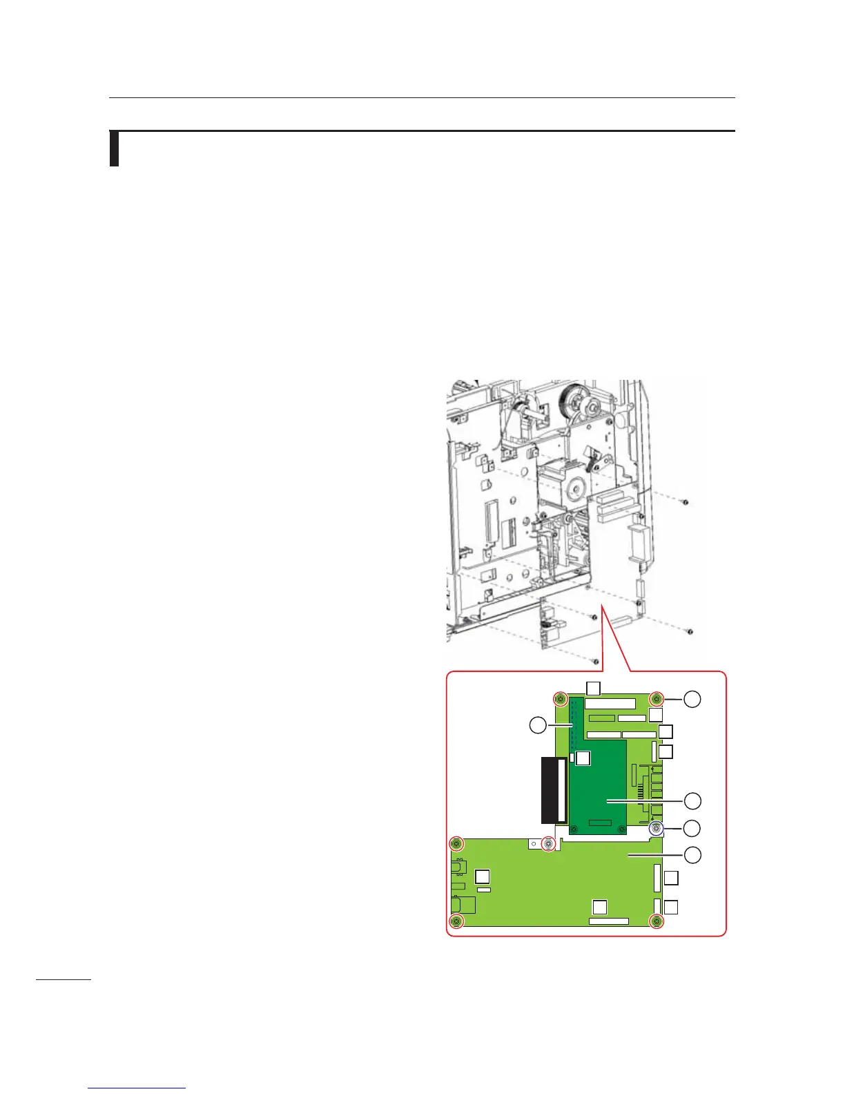
4 Remove six screws 3 attaching the
main (CONT) PCB
. to the bracket.
For CL4NX, skip step 5 and step 6 and then
continue from step 7.
Step 5 and step 6 is only applicable for CL6NX.
5 Remove a screw $ attaching the FPGA
PCB assembly
/ to the main (CONT)
PCB
. and bracket.
6 Remove the FPGA PCB assembly /
from the FPGA connector
1 on the
main (CONT) PCB
..
7 Replace the defective main (CONT)
PCB
.with a new main (CONT) PCB.
 Loading...