1 Introduction
6
CL4NX/CL6NX Service Manual
1.3
Parts Identification of the Printer
For the parts identification of the external view of the printer, refer to Section 1.1 Parts Identification of
the Printer of
CL4NX/CL6NX operator manual.
Note
The pictures in this manual show the CL4NX printer, unless otherwise stated.
1.3.1
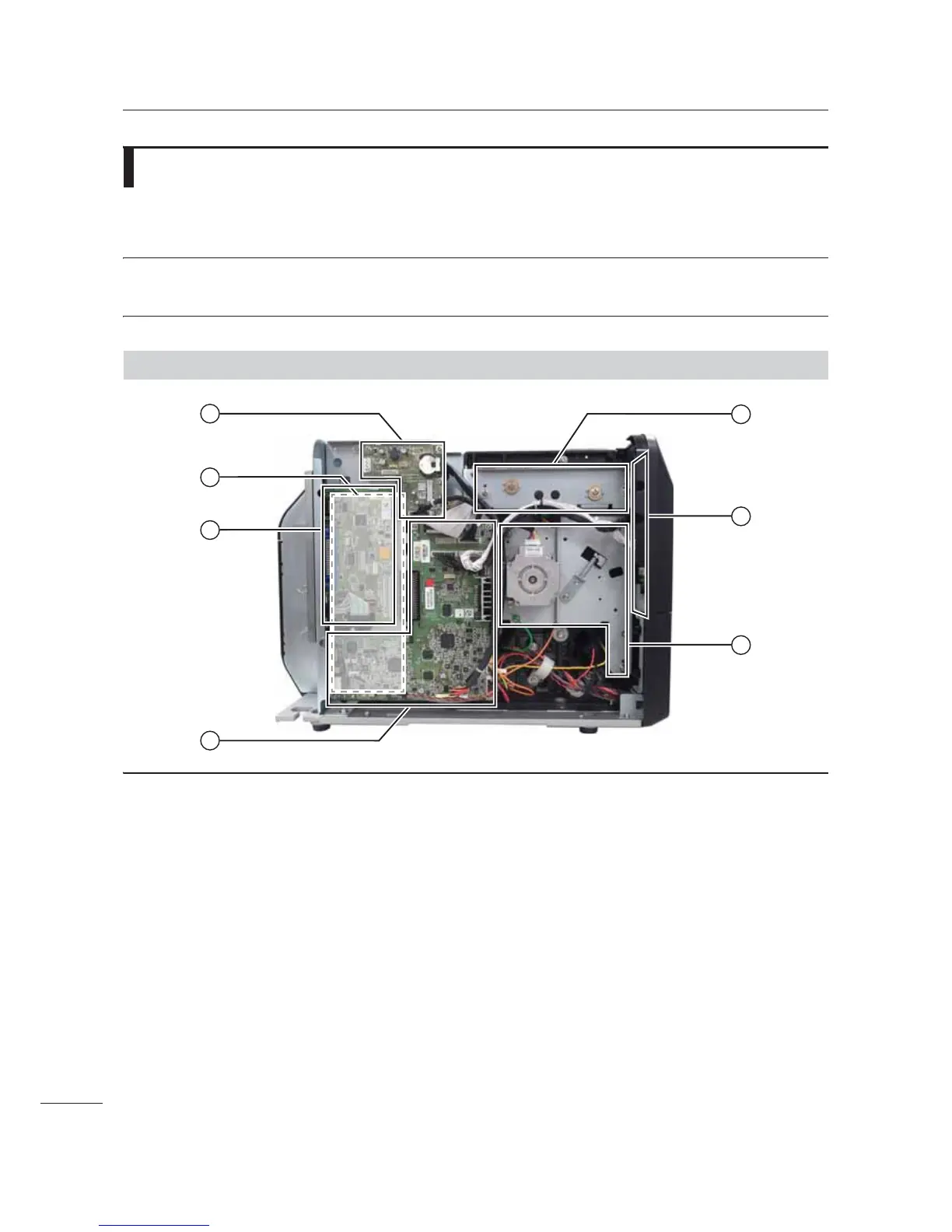
Internal View with Left Housing Cover Removed (CL4NX)
1
4
3
5
7
6
2
.
Optional EXT PCB board
The optional EXT PCB is added when
installing the optional RTC (Real Time Clock)
kit, dispenser unit or RFID kit.
3
Power supply unit
This is the power board, which is located
behind the main (CONT) PCB. It contains the
printer’s transformers, relays, etc., for
transference of electrical current from the
supply source to the printer’s control circuits.
$
Interface board
/
Main (CONT) PCB board
The main (CONT) PCB is the primary brain
center for all printer activities.
1
Ribbon frame
To support the ribbon supply spindle and
ribbon rewind spindle.
4
Operator panel (KB) PCB board
This PCB provides the user interaction
functionality via the operational buttons and as
well as the LCD.
2
Gearbox
The stepper motor, timing belt and gears in the
gearbox provide the main rotation motion for
precise print positioning.
 Loading...