3 Functions Issue 10/06
MICROMASTER 440 Operating Instructions
104 6SE6400-5AW00-0BP0
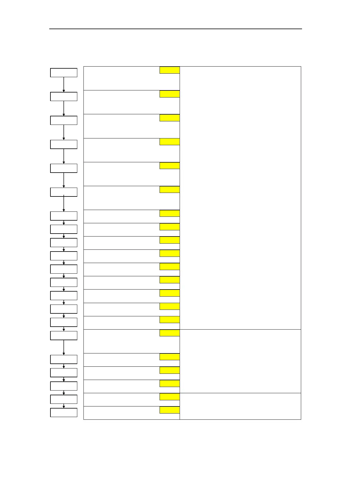
3.5.7.9 Fixed frequency (FF)
Fixed frequency 1
Can be directly selected via DIN1
(P0701 = 15, 16)
Fixed frequency 2
Can be directly selected via DIN2
(P0702 = 15, 16)
Fixed frequency 3
Can be directly selected via DIN3
(P0703 = 15, 16)
Fixed frequency 4
Can be directly selected via DIN4
(P0704 = 15, 16)
Fixed frequency 5
Can be directly selected via DIN5
(P0705 = 15, 16)
Fixed frequency 6
Can be directly selected via DIN6
(P0706 = 15, 16)
Fixed frequency 7
Fixed frequency 8
Fixed frequency 9
Fixed frequency 10
Fixed frequency 11
Fixed frequency 12
Fixed frequency 13
Fixed frequency 14
Fixed frequency 15
When defining the function of the digital inputs
(P0701 to P0703), three different types can be
selected for fixed frequencies:
15 = Direct selection (binary-coded)
In this particular mode, the appropriate
digital input always selects the associated
fixed frequency, e.g.:
Digital input 3 = selects fixed frequency 3.
If several inputs are simultaneously active,
then these are summed. An ON command is
additionally required.
16 = Direct selection + ON command
(binary-coded + On / Off1)
In this mode, the fixed frequencies are
selected as for 15, however these are
combined with an ON command.
17 = Binary coded selection + ON command
(BCD-coded + On/ Off1)
The BCD-coded operating mode is effective for
digital inputs 1 to 3.
Fixed frequency code - Bit 0
Defines the selection method for fixed
frequencies.
Fixed frequency code - Bit 1
Fixed frequency code - Bit 2
Fixed frequency code - Bit 3
1 Direct selection
2 Direct selection + ON command
3 Binary coded selection + ON command
NOTE
For settings 2 and 3, all parameters P1016 to
P1019 must be set to the selected value so that
the drive inverter accepts the ON command.
Fixed frequency code - Bit 4
Fixed frequency code - Bit 5
1 Direct selection
2 Direct selection + ON command
1
1
1
P1016 = ...
P1017 = ...
P1018 = ...
1
P1019 = ...
1
P1025 = ...
1
P1027 = ...
5.00 Hz
10.00 Hz
15.00 Hz
20.00 Hz
25.00 Hz
0.00 Hz
P1001 = ...
P1002 = ...
P1003 = ...
P1004 = ...
P1005 = ...
P1006 = ...
30.00 Hz
P1007 = ...
P1008 = ...
35.00 Hz
P1009 = ...
40.00 Hz
P1010 = ...
45.00 Hz
P1011 = ...
50.00 Hz
P1012 = ...
55.00 Hz
P1013 = ...
60.00 Hz
P1014 = ...
65.00 Hz
P1015 = ...
65.00 Hz
 Loading...