2 Installation Issue 10/06
MICROMASTER 440 Operating Instructions
42 6SE6400-5AW00-0BP0
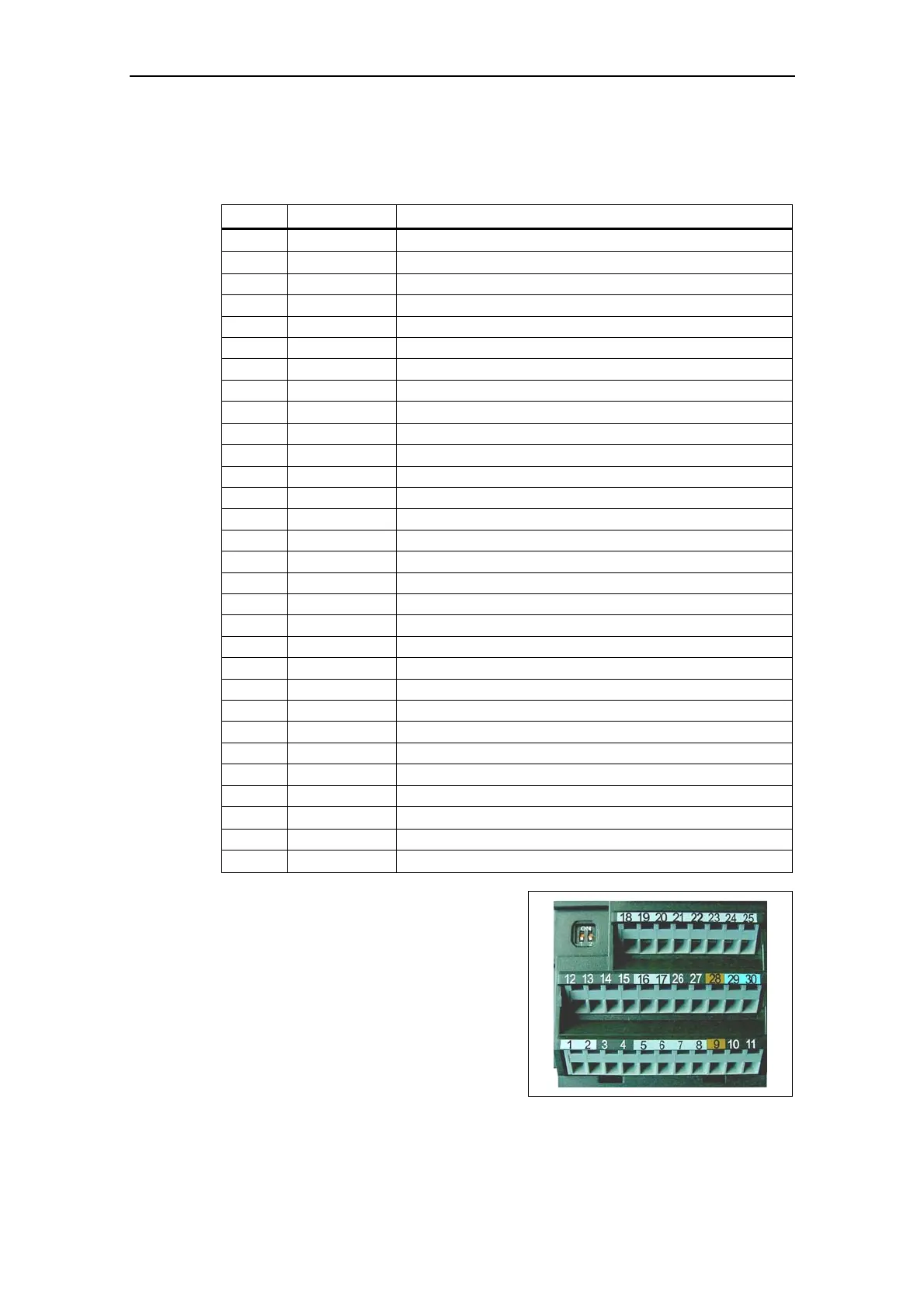
2.4.3 Control terminals
Permitted cable diameters: 0.08 … 2.5 mm
2
(AWG: 28 … 12)
Terminal Designation Function
1
−
Output +10 V
2
−
Output 0 V
3 ADC1+ Analog input 1 (+)
4 ADC1- Analog input 1 (-)
5 DIN1 Digital input 1
6 DIN2 Digital input 2
7 DIN3 Digital input 3
8 DIN4 Digital input 4
9
−
Isolated output +24 V / max. 100 mA
10 ADC2+ Analog input 2 (+)
11 ADC2- Analog input 2 (-)
12 DAC1+ Analog output 1 (+)
13 DAC1- Analog output 1 (-)
14 PTCA Connection for PTC / KTY84
15 PTCB Connection for PTC / KTY84
16 DIN5 Digital input 5
17 DIN6 Digital input 6
18 DOUT1/NC Digital output 1 / NC contact
19 DOUT1/NO Digital output 1 / NO contact
20 DOUT1/COM Digital output 1 / Changeover contact
21 DOUT2/NO Digital output 2 / NO contact
22 DOUT2/COM Digital output 2 / Changeover contact
23 DOUT3/NC Digital output 3 / NC contact
24 DOUT3/NO Digital output 3 / NO contact
25 DOUT3/COM Digital output 3 / Changeover contact
26 DAC2+ Analog output 2 (+)
27 DAC2- Analog output 2 (-)
28
−
Isolated output 0 V / max. 100 mA
29 P+ RS485 port
30
N−
RS485 port
Fig. 2-13 Control terminals of
MICROMASTER 440
A detailed description of the inputs and outputs is provided in Section 3.6.
 Loading...