3 Functions Issue 10/06
MICROMASTER 440 Operating Instructions
98 6SE6400-5AW00-0BP0
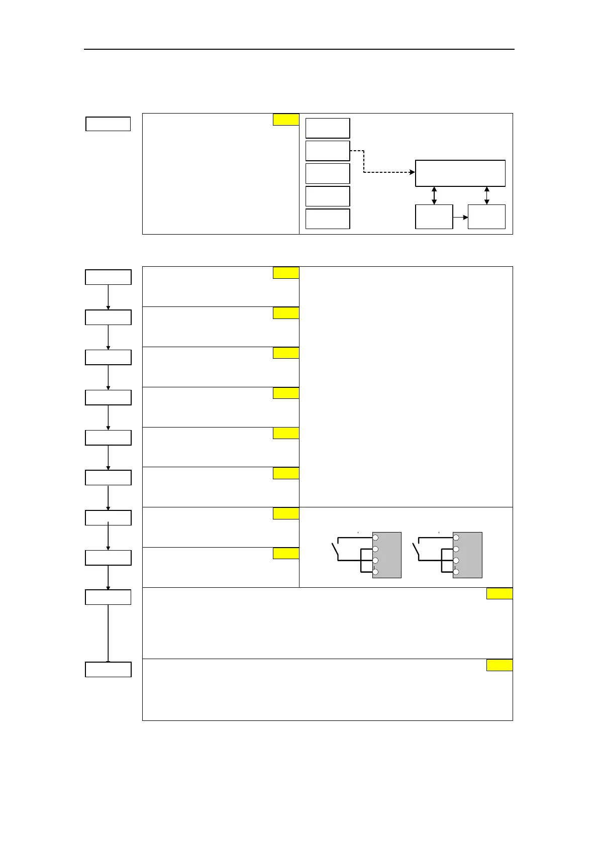
3.5.7.2 Selection of command source
P0700 =...
Selection of
command source
Selects digital command source.
0 Factory fault setting
1 BOP (keypad)
2 Terminal
4 USS on BOP link
5 USS on COM link
6 CB on COM link
P0700 = 2
Sequence control
Setpoint
channel
Motor
control
BOP
USS
BOP link
USS
COM link
Terminals
CB
COM link
3.5.7.3 Digital input (DIN)
Function digital input 1
Terminal 5
1 ON / OFF1
Function digital input 2
Terminal 6
12 Reverse
Function digital input 3
Terminal 7
9 Fault acknowledge
Function digital input 4
Terminal 8
15 Fixed setpoint (Direct selection)
Function digital input 5
Terminal 16
15 Fixed setpoint (Direct selection)
Function digital input 6
Terminal 17
15 Fixed setpoint (Direct selection)
Possible Settings:
0 Digital input disabled
1 ON / OFF1
2 ON + Reverse / OFF1
3 OFF2 – coast to standstill
4 OFF3 – quick ramp-down
9 Fault acknowledge
10 JOG right
11 JOG left
12 Reverse
13 MOP up (increase frequency)
14 MOP down (decrease frequency)
15 Fixed setpoint (Direct selection)
16 Fixed setpoint (Direct selection + ON)
17 Fixed setpoint (Binary coded selection + ON)
21 Local/remote
25 DC brake enable
29 External trip
33 Disable additional freq setpoint
99 Enable BICO parameterization
Function digital input 7
Via analog input, Terminal 3
0 Digital input disabled
Function digital input 8
Via analog input, Terminal 10
0 Digital input disabled
DIN8
DIN7
ON > 3,9 V, OFF < 1,7 V
1
2
10
11
1
2
3
4
Debounce time for digital inputs
Defines debounce time (filtering time) used for digital inputs.
0 No debounce time
1 2.5 ms debounce time
2 8.2 ms debounce time
3 12.3 ms debounce time
PNP / NPN digital inputs
Change-over (toggles) between high active (PNP) and low active (NPN). This applies to all
digital inputs simultaneously.
0 NPN mode ==> low active
1 PNP mode ==> high active
15
P0706 = ...
15
P0705 = ...
1
12
9
15
P0701 = ...
P0703 = ...
P0702 = ...
P0704 = ...
3
P0724 = ...
P0725 = ...
1
0
P0707 = 0
0
P0708 = 0
2
 Loading...