Issue 10/06 3 Functions
MICROMASTER 440 Operating Instructions
6SE6400-5AW00-0BP0
127
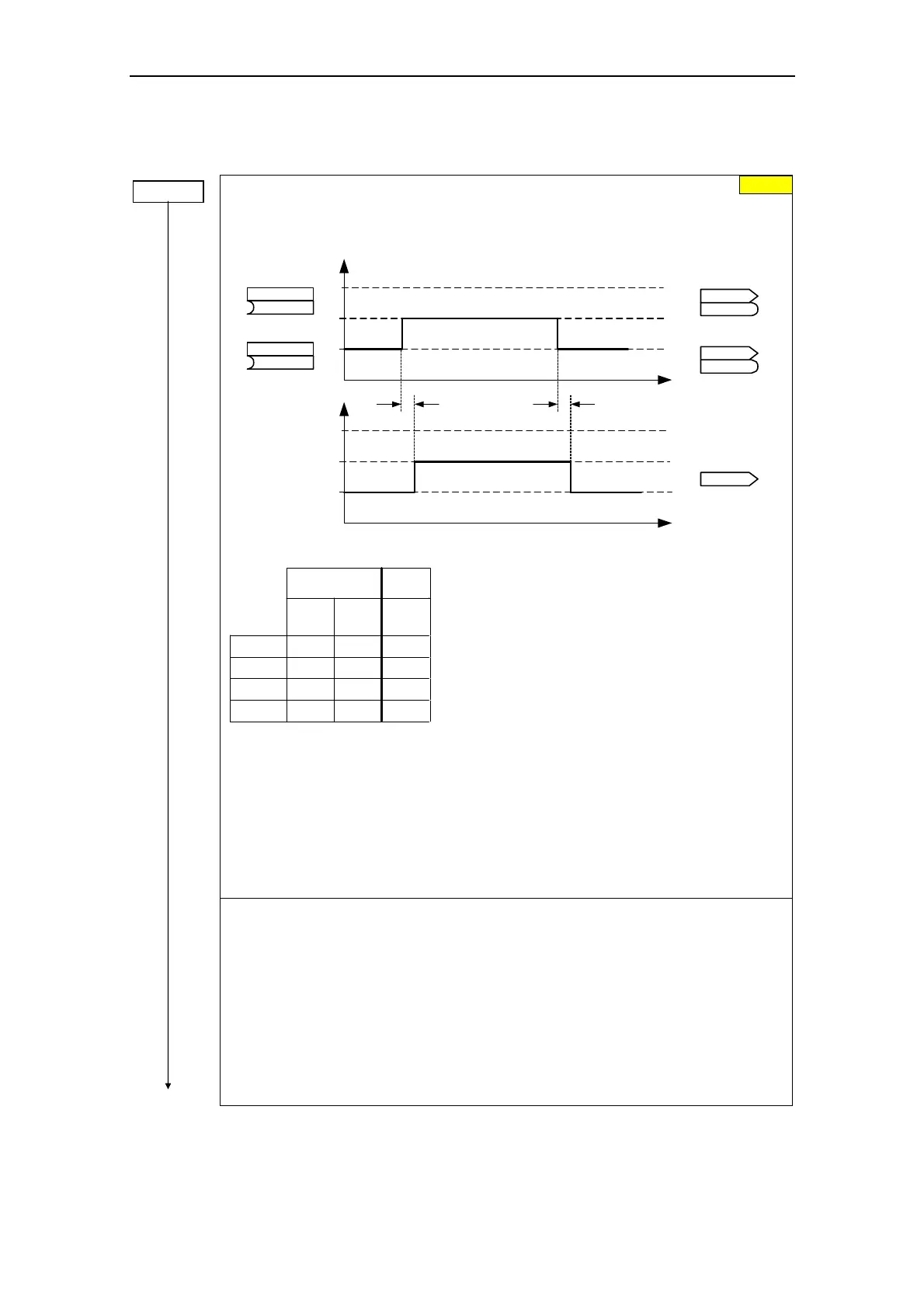
3.5.7.19 Command and drive data set
P0810 =...
Command data set CDS bit 0 (local / remote)
Selects the command source in which bit 0 should be read-out to select a command data
set (CDS).
t0
1
2
3
(0:0)
BI: CDS b0 loc/rem
P0810
(0:0)
BI: CDS bit 1
P0811
t0
1
2
3
CO/BO: Act CtrlWd2
r0055
r0055
CO/BO: Act CtrlWd1
r0054
r0054
.15
.15
.15
.15
r0050
Active CDS
Selecting CDS
approx. 4 ms approx. 4 ms
r0050
CO: Active CDS
Changeover timeChangeover time
The currently active command data set (CDS) is displayed using parameter r0050:
r0055
bit15
r0054
bit15
1. CDS 0 0
2. CDS 0 1
3. CDS 1 0
3. CDS 1 1
r0050
0
1
2
2
Select
CDS
Active
CDS
Most frequent settings:
722.0 = Digital input 1 (P0701 must be set to 99, BICO)
722.1 = Digital input 2 (P0702 must be set to 99, BICO)
722.2 = Digital input 3 (P0703 must be set to 99, BICO)
722.3 = Digital input 4 (P0704 must be set to 99, BICO)
722.4 = Digital input 5 (P0705 must be set to 99, BICO)
722.5 = Digital input 6 (P0706 must be set to 99, BICO)
722.6 = Digital input 7 (via analog input 1, P0707 must be set to 99)
722.7 = Digital input 8 (via analog input 2, P0708 must be set to 99)
Example for CDS changeover:
CDS1: Command source via terminals and setpoint source via analog input (ADC)
CDS2: Command source via BOP and setpoint source via MOP
CDS changeover is realized using digital input 4 (DIN 4)
Steps:
1. Carry-out commissioning for CDS1 (P0700[0] = 2 and P1000[0] = 2)
2. Connect P0810 (P0811 if required) to the CDS changeover source
(P0704[0] = 99, P0810 = 722.3)
3. Copy from CDS1 to CDS2 (P0809[0] = 0, P0809[1] = 1, P0809[2] = 2)
4. Adapt CDS2 parameters (P0700[1] = 1 and P1000[1] = 1)
0
 Loading...