3 Functions Issue 10/06
MICROMASTER 440 Operating Instructions
202 6SE6400-5AW00-0BP0
3.15 Electronic brakes
MICROMASTER 440 has 3 electronic brakes:
DC braking (refer to Section 3.15.1)
Compound braking (refer to Section 3.15.2)
Dynamic braking (refer to Section 3.15.3)
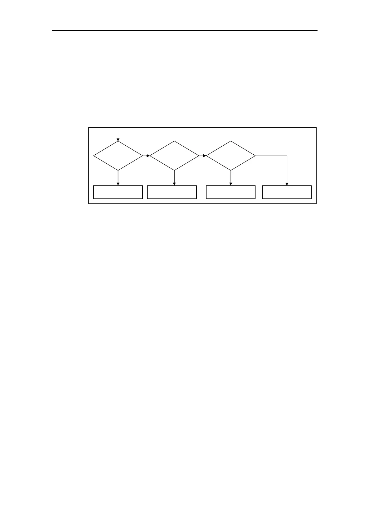
These brakes can actively brake the drive and avoid a possible DC link overvoltage
condition. An inter-dependency as shown in Fig. 3-72 is present.
DC braking
P1233 > 0
?
yes
no
DC braking
enabled
Compound
braking
P1236 > 0
?
Compound braking
enabled
Dynamic
braking
P1237 > 0
?
Dynamic braking
enabled
disabled
no no
yes yes
Fig. 3-72 Inter-dependency of the electronic brakes
3.15.1 DC braking
Parameter range: P1230, P1233
P1232, P1234
r0053 Bit00
Warnings -
Faults -
Function chart number: -
The drive decelerates along a parameterized braking ramp if an OFF1 / OFF3
command is output. A "flat" ramp must be selected so that the drive inverter is not
tripped (shutdown) due to the high regenerative energy which would cause a DC
link overvoltage condition. The DC brake should be activated while the OFF1 /
OFF3 command is present if the drive is to be braked faster. For DC braking,
instead of continually reducing the output frequency / voltage during the OFF1 /
OFF3 phase, from a selectable frequency, a DC voltage / current is input (refer to
sequence a).
The drive can be brought to a standstill in the shortest time using DC current
braking (DC brake). DC braking is selected as follows:
¾ After OFF1 or OFF3 (the DC brake is released via P1233) Sequence ℵ
¾ Directly selected using BICO parameter P1230 Sequence ℑ
For DC braking, a DC current is impressed in the stator winding which results in a
significant braking torque for an induction motor. The magnitude, duration and
frequency at which braking starts can be set for the braking current and therefore
braking torque by setting the appropriate parameters.
 Loading...