3 Functions Issue 10/06
MICROMASTER 440 Operating Instructions
68 6SE6400-5AW00-0BP0
3.1.4 Reference quantities
Parameter range: P2000 – r2004
Physical quantities are normalized or de-normalized by the frequency inverter
when data is output or is being entered. This conversion is undertaken by the
particular interface using the reference quantities. The normalization / de-
normalization is carried-out for the following interfaces:
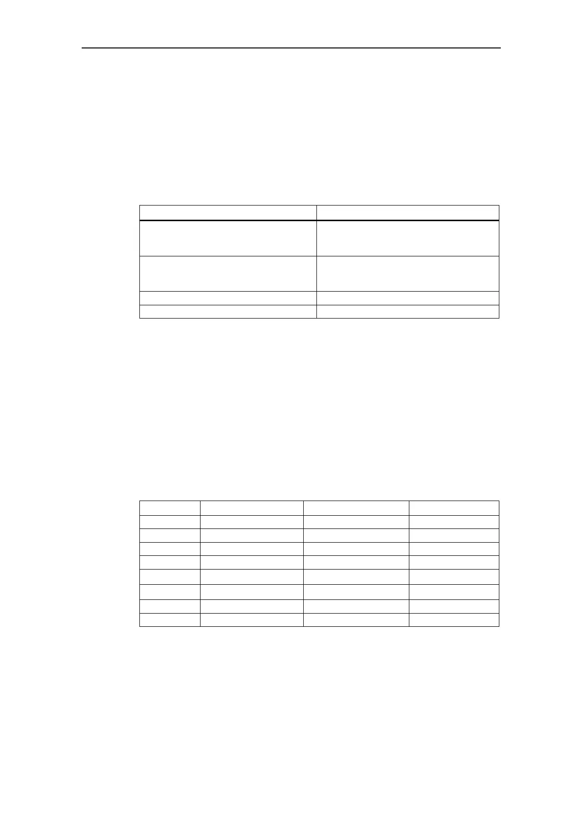
Table 3-5 Normalized interfaces
Interafce 100 %
Analog input
Current input
Voltage input
20 mA
10 V
Analog output
Current output
Voltage output
20 mA
10 V
USS 4000 h
CB 4000 h
Further, for a BICO connection, a normalization is carried-out if the connector
output (CO) represents a physical quantity and the connector input (CI) a
normalized (percentage) quantity (e.g. PID controller). De-normalization is carried-
out if the inverse situation exists. This normalization / de-normalization should be
carefully taken into consideration, especially for the free function blocks (FFBs).
Reference quantities (normalization quantities) are intended to allow setpoint and
actual value signals to be represented in a standard fashion (normalization / de-
normalization of physical quantities such as setpoint and actual frequency). This
also applies for permanently set parameters that are entered as a "percentage". A
value of 100 % corresponds to a process data value PZD of 4000 h (USS or CB) –
or a current / voltage value of 20 mA / 10 V (analog input / output). The following
reference parameters and permanently saved reference values are available:
Table 3-6 Normalization functions
Parameter Designation Value (100 % / 4000 h) Units
P2000 Reference frequency P2000 Hz
P2001 Reference voltage P2001 V
P2002 Reference current P2002 A
P2003 Reference torque P2003 Nm
r2004 Reference power
π
*
P2000
*
P2003
kW
- Reference speed
P2000
*
60 / r0313
RPM
- Reference temperature 100 °C °C
- Reference energy 100 kWh kWh
 Loading...