3 Functions Issue 10/06
MICROMASTER 440 Operating Instructions
80 6SE6400-5AW00-0BP0
By changing the setting of DIP50/60 switch, after the drive inverter has been
powered-down/powered-up, the parameters for the rated motor frequency P0310,
max. frequency P1082 and reference frequency P2000 are automatically pre-set.
In addition, the rated motor parameters as well as all of the other parameters which
depend on the rated motor parameters, are reset. The units of the power
parameters are, depending on P0100, are either interpreted as kW value or hp
value.
NOTE
Switch DIP2(1) (refer to Fig. 3-21) under the I/O board has no function.
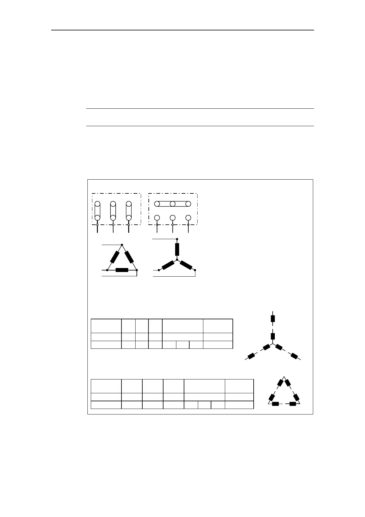
3.5.2 Motor circuit
In order to ensure a straightforward, successful commissioning, it is important that
the circuit connection in the motor terminal box (refer to Fig. 3-23) matches the
rated motor voltage entered in P0304 or the rated motor current P0305.
W2
U1
U2
V1
V2
W1
W2
U1
U2
V1
V2
W1
Delta connection
U1
V1
W1
U1
V1
W1
Star connection
IEC Motor
e.g.: Volts 230 V (Delta connection) / 400 V (Star connection)
NEMA Motor
T
1
T
4
T
7
T
3
T
6
T
9
T
8
T
5
T
2
Volts
UVW
T
1
-T
7
T
2
-T
8
T
3
-T
9
low
T
4
-T
5
-T
6
T
1
T
2
T
3
high
Connected
together
Connection
T
1
-T
7
T
2
-T
8
T
3
-T
9
Y Y
Y
UVW
T
1
-T
6
-T
7
T
2
-T
4
-T
8
T
3
-T
5
-T
9
-
T
1
T
2
T
3
T
4
-T
7
T
5
-T
8
T
6
-T
9
∆ ∆
∆
T
1
T
4
T
7
T
2
T
5
T
8
T
3
T
9
T
6
e.g.: Volts 230 V YY (low) / 460 V Y (high)
Volts
low
high
Connected
together
Connection
Fig. 3-23 Motor terminal box
 Loading...