Issue 10/06 3 Functions
MICROMASTER 440 Operating Instructions
6SE6400-5AW00-0BP0
91
3.5.5 Motor data identification
MICROMASTER has a measuring technique which is used to determine the motor
parameters:
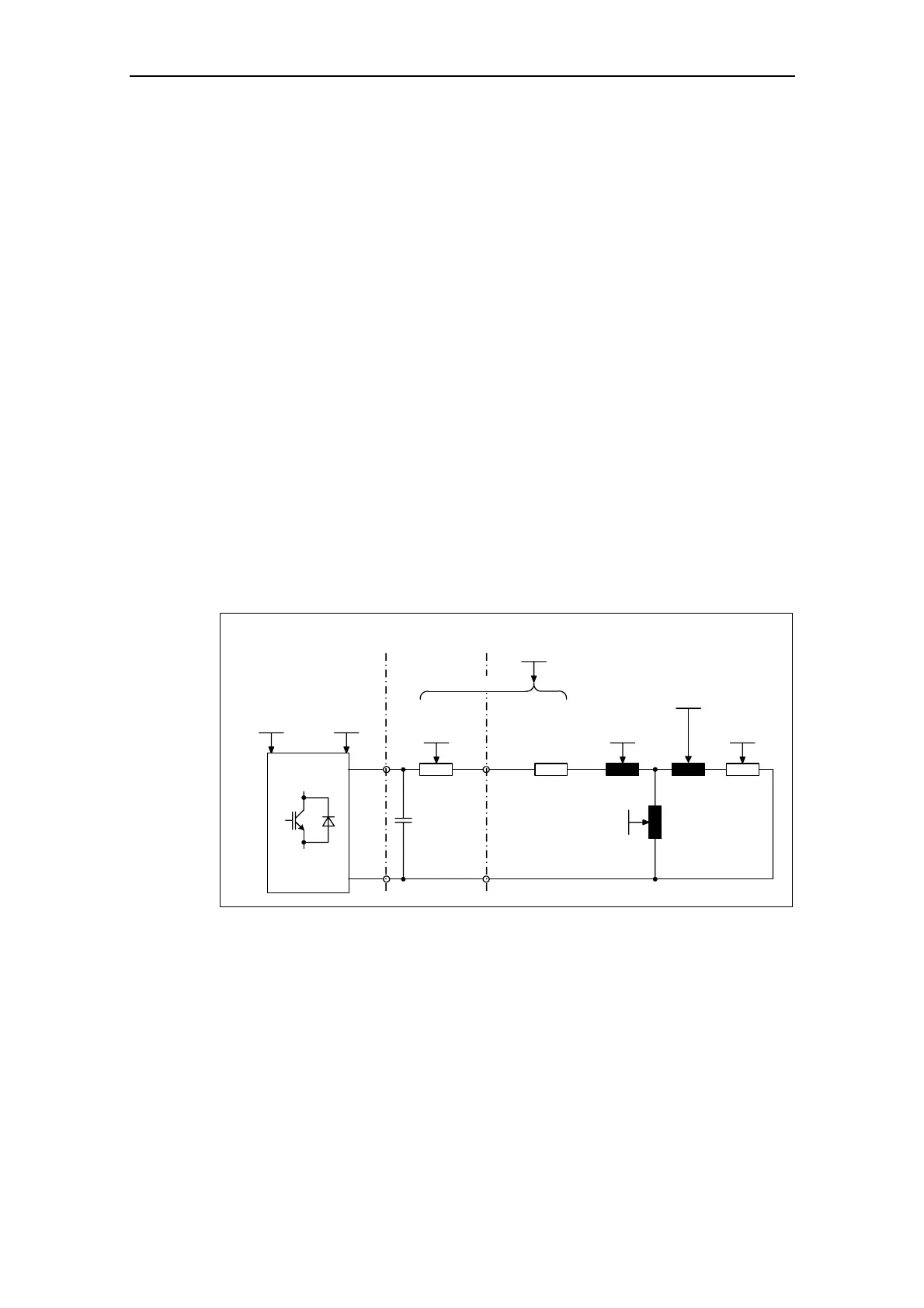
¾ Equivalent circuit data (ECD, refer to Fig. 3-26) → P1910 = 1
¾ Magnetizing characteristic (refer to Fig. 3-27) → P1910 = 3
For control-related reasons, we absolutely recommend that the motor data
identification is carried-out as, starting from the rating plate data, it is only possible
to estimate the equivalent circuit data, the motor cable resistance, the IGBT let-
through voltage and the compensation of IGBT interlocking times. For example, the
stator resistance is extremely important for the stability of the closed-loop Vector
control and for the voltage boost for the V/f characteristic. The motor data
identification routine should be executed, especially if long feeder cables or if third-
party motors are being used.
If the motor data identification routine is being started for the first time, then the
following data (refer to Fig. 3-26) is determined, starting from the rating plate data
(rated [nominal] data) with P1910 = 1:
¾ Equivalent circuit data
¾ Motor cable resistance
¾ IGBT on-state voltage and compensation of IGBT gating dead times
The rating plate data represent the initialization values for the identification. This is
the reason that it is necessary to have correct and consistent input of the rating
plate data when determining the data specified above (refer to Section 3.5.8).
Cable resistance
0.0 ... 120.0 [Ohm]
P0352.D (0.0)
Stator leak.induct
0.00001 ... 1000.00000
P0356.D (10.00000)
L
?S
Rotor leak.induct.
0.0 ... 1000.0
P0358.D (10.0)
L
?R
L
M
Main inductance
0.0 ... 3000.0
P0360.D (10.0)
Rotor resistance
0.0 ... 300.0 [Ohm]
P0354.D (10.0)
R
R
On-state voltage
0.0 ... 20.0 [V]
P1825 (1.4)
Gating dead time
0.00 ... 3.50 [us]
P1828 (0.50)
MotorCableInverter
Stator res. (L2L)
0.00001 ... 2000.00000 [Ohm]
P0350.D (4.00000)
C
R
Cable
Cable
R
S
Cable
P0350 = 2(R + R
S
)
Fig. 3-26 Equivalent circuit diagram (ECD)
In addition to the equivalent circuit data, the motor magnetizing characteristic (refer
to Fig. 3-26) can be determined using the motor data identification (P1910 = 3). If
the motor-drive inverter combination is operated in the field-weakening range, then
this characteristic should be determined, especially when Vector control is being
used. As a result of this magnetizing characteristic, MICROMASTER can, in the
field-weakening range, more precisely calculate the current which is generating the
field and in turn achieve a higher torque accuracy.
 Loading...