3 Functions Issue 10/06
MICROMASTER 440 Operating Instructions
170 6SE6400-5AW00-0BP0
3.9 Motorized potentiometer (MOP)
Parameter range: P1031 – r1050
Warnings -
Faults -
Function chart number: FP3100
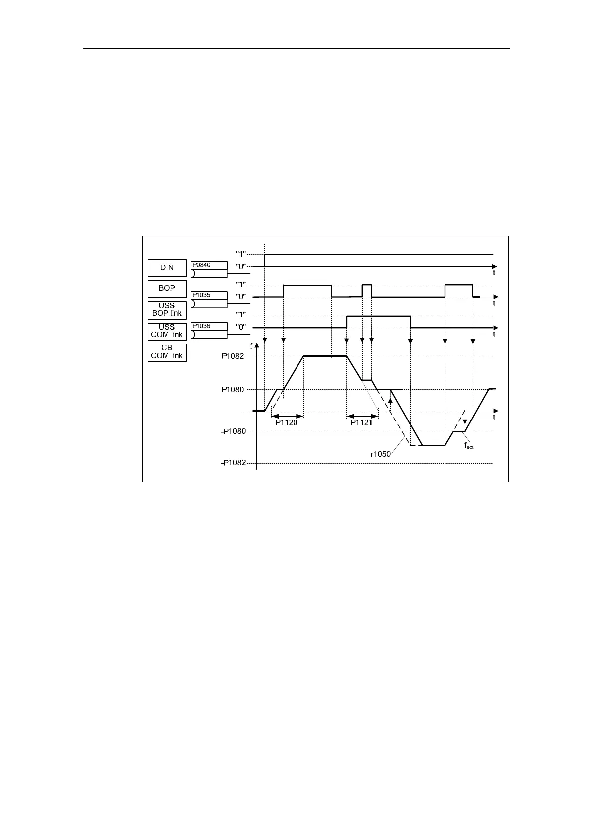
This function emulates an electromechanical potentiometer to enter setpoints. The
motorized potentiometer value is adjusted using the "Raise" and "Lower control
signal" which is selected using BICO parameters P1035 and P1036 (refer to Fig.
3-51). The value which has been set is available through connector output r1050
so that it can be further connected and used.
Fig. 3-51 Motorized potentiometer
Selecting via serial interfaces
The MOP functionality can be selected via the operator panels (refer to Section
3.2), digital inputs as well as via serial interfaces (refer to the example).
Parameterization is also possible directly using BICO parameters P1035 and
P1036 as well as also parameters P0700 and P0719. In this case, for a value
assigned to P0700, the BICO parameter is appropriately modified.
Example: Command source via "USS on BOP link" interface
a) Standard method
→ P0700 = 4
b) BICO method → P1035 = 2032.13
P1036 = 2032.14
::::
(refer to P0700 for a complete list)
 Loading...