Description
1.5 Representation of SIMOTION D445
SIMOTION D4x5
22 Manual, 02/2012
1.5 Representation of SIMOTION D445
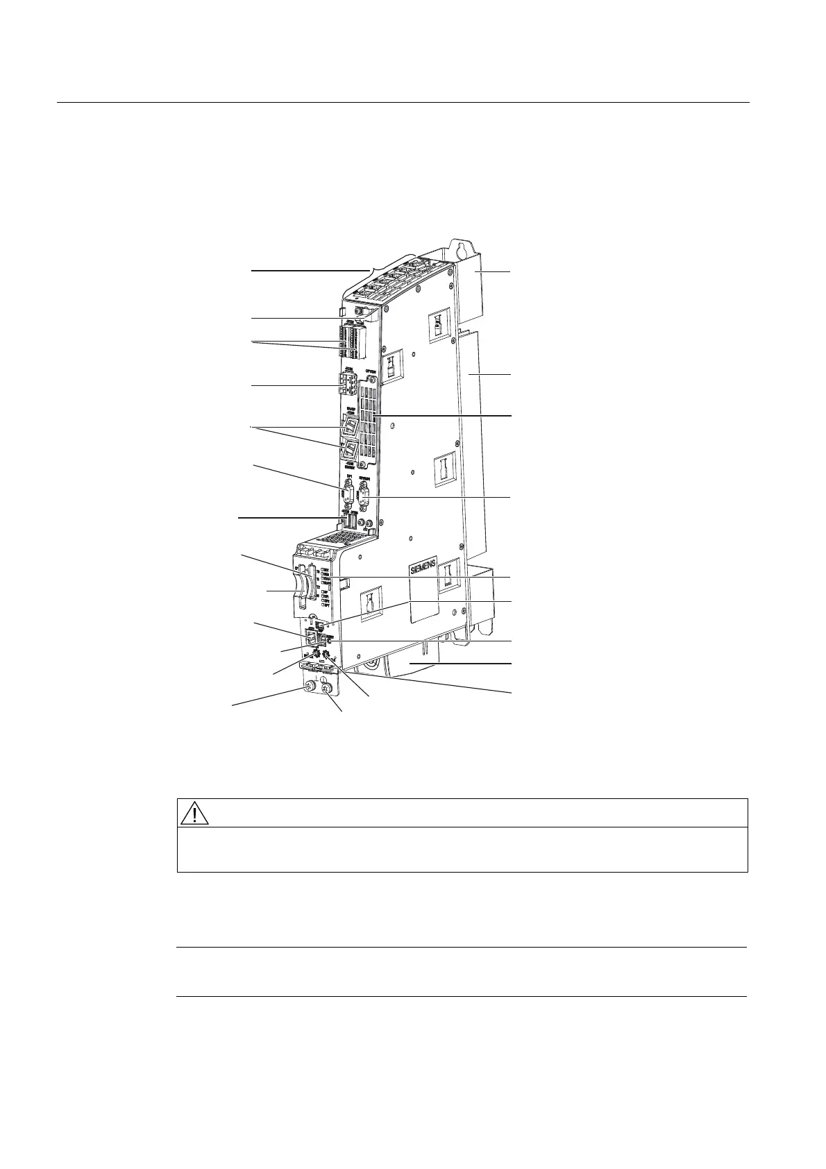
The following figure shows the SIMOTION D445 with its interfaces and front panel elements
(fault and status displays).
;;
'5,9(&/L4LQWHUIDFHV
6KLHOGFRQQHFWLRQ
;;
'LJLWDOLQSXWVRXWSXWV
;
(OHFWURQLFSRZHUVXSSO\
;;
(WKHUQHWLQWHUIDFHV
2SWLRQVORW
&RROLQJILQV
6SDFHUDOZD\V
UHTXLUHG
;
352),%86'3
;
352),%86'303,
86%[
ULJKW;
OHIW;
;
&RPSDFW)ODVKFDUG
;
)DQEDWWHU\PRGXOH
/('GLVSOD\V
VHJPHQWGLVSOD\
UHOHYDQWIRUVHUYLFHRQO\
;XQGHUVLGH
56QRIXQFWLRQ
5(6(7EXWWRQ
0RGHVZLWFK
;;
0HDVXULQJVRFNHWV
%23LQWHUIDFHQR
IXQFWLRQ
6HUYLFHVHOHFWRUVZLWFK
(WKHUQHWLQWHUIDFH
QRIXQFWLRQ
(TXLSRWHQWLDO
ERQGLQJFRQQHFWLRQ
01P7RU[7
3URWHFWLYHFRQGXFWRU
FRQQHFWLRQ01P7RU[7
Figure 1-3 Location of interfaces and front panel elements of SIMOTION D445
CAUTION
SIMOTION D445 must be operated with a fan / battery module for heat dissipation. Without
a fan/battery module, the control unit will not start up and cannot be commissioned.
A description of how to install the fan/battery module can be found in "Spare
Parts/Accessories" Installing the fan/battery module (Page 77).
Note
The spacers cannot be removed in the case of the SIMOTION D445.

 Loading...


