EasyManua.ls Logo

Siemens SIMOTION D4 5 Series User Manual

Siemens SIMOTION D4 5 Series
130 pages
To Next Page IconTo Next Page
To Previous Page IconTo Previous Page
Page #91 background image
Supplementary system components
6.4 Controller Extension CX32
SIMOTION D4x5
Manual, 02/2012
91
6.4.2.1 List of interfaces
The CX32 has the following interfaces:
4 DRIVE-CLiQ interfaces
4 digital inputs/outputs
4 digital inputs
Power supply connector
Available interfaces
Table 6- 12 Overview of available interfaces
Interface Name Connector type
DRIVE-CLiQ interface X100 DRIVE-CLiQ socket
DRIVE-CLiQ interface X101 DRIVE-CLiQ socket
DRIVE-CLiQ interface X102 DRIVE-CLiQ socket
DRIVE-CLiQ interface X103 DRIVE-CLiQ socket
Digital inputs/outputs X122 Micro Combicon, 1x12-pin
Power supply connector X124 Combicon, 4-pin
Measuring sockets (T0, T1, T2, and M) X131 - X134 Sockets
Non-usable interfaces
Table 6- 13 Overview of interfaces that cannot be used for the CX32
Interface name Interface Connector type
RS 232 interface (as of HW version B) X140 9-pin Sub-D connector

Table of Contents

Question and Answer IconNeed help?

Do you have a question about the Siemens SIMOTION D4 5 Series and is the answer not in the manual?
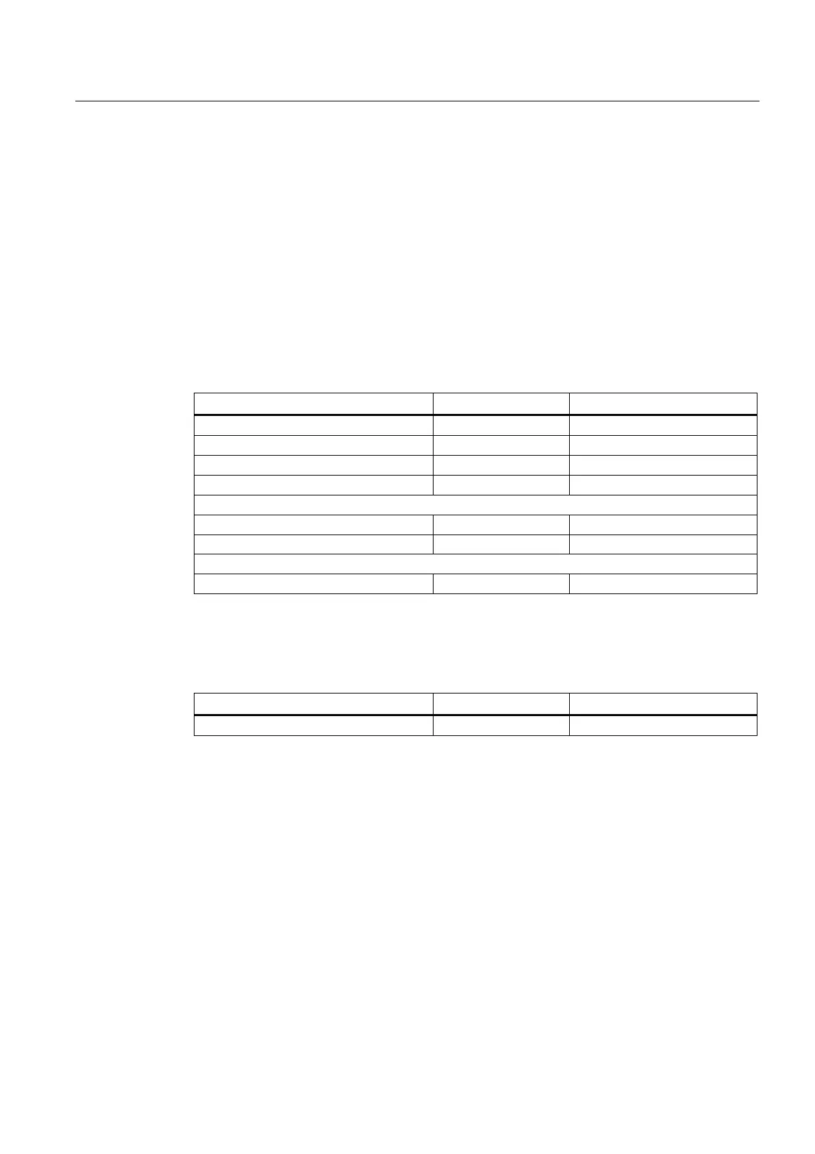
Siemens SIMOTION D4 5 Series Specifications

General IconGeneral
Power Supply24 V DC
Product type designationSIMOTION D445
Communication InterfacesPROFIBUS, PROFINET, Ethernet, USB
Operating Temperature0 to 55 °C
Memory Size512 MB RAM
Operating SystemReal-time operating system (RTOS)
Ethernet Ports2
USB Ports2
Number of AxesUp to 128 axes

Summary

SIMOTION D4x5 Description

System Overview

Provides a general overview of the SIMOTION D system and its versions.

System Components

Details the central and optional components of the SIMOTION D system.

Safety Notes

Provides essential safety information for handling the control unit.

SIMOTION D4x5 Operator Control (Hardware)

Operator Control and Display Elements Overview

Shows the arrangement of control and display elements on the SIMOTION D4x5.

Operator Control Elements

Describes control elements like mode and service selector switches.

7-Segment and LED Displays

Explains the meaning and function of the 7-segment and LED displays.

SIMOTION D4x5 Interfaces

DRIVE-CLiQ Interfaces

Details the DRIVE-CLiQ interface characteristics and pin assignment.

Ethernet Interfaces

Explains the Ethernet interfaces, features, and pin assignments.

SIMOTION D4x5 Technical Data

Technical Data D4x5

Covers memory, CF card, dimensions, weight, and ambient conditions.

SIMOTION D4x5 Supplementary System Components

Fan/Battery Module

Details the functions and installation of the fan/battery module.

Controller Extension CX32

Explains the CX32 controller extension and its drive quantity structures.

CBE30 Communication Board Ethernet

Details the CBE30 Ethernet board, its features, and safety.

SIMOTION D4x5 Standards and Approvals

Safety of Electronic Controllers

Discusses fundamental safety criteria for electronic controllers.

SIMOTION D4x5 ESD Guidelines

Basic Measures for Protection Against Discharge

Outlines essential measures for grounding and avoiding ESD.

Related product manuals