Operator control (hardware)
2.2 Operator control elements
SIMOTION D4x5
Manual, 02/2012
35
2.2 Operator control elements
2.2.1 Service and operating mode switch
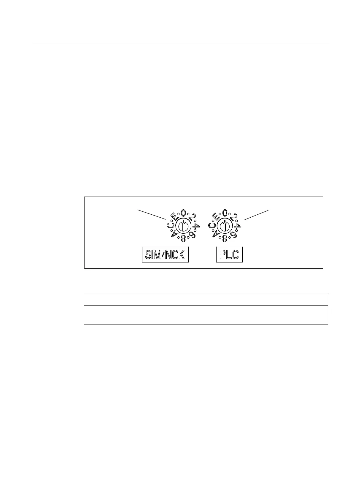
Properties of the service and operation mode switch
SIMOTION D4x5 has a Service selector switch and an operating mode selector switch in the
lower section of the front panel.
The switch on the right labeled PLC is used for switching the operating mode of the
SIMOTION D4x5.
The Service selector switch on the left (labeled SIM/NCK) is for service and diagnosis
functions only. In "normal" operation this switch must remain in the 0 position (see figure
below).
0RGHVHOHFWRUVZLWFK6HUYLFHVHOHFWRU
VZLWFK
Figure 2-4 Mode selector and Service selector switch SIMOTION D4x5
CAUTION
Always use an insulated screwdriver to turn the rotary switch. Otherwise, static electricity
can destroy the switch.

 Loading...


