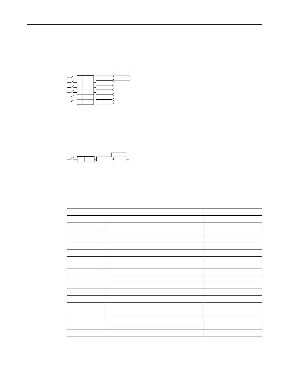
8.4.1 Digital inputs
Function description
',
',
',
',
',
',
U
U
U
U
U
U
%,S[[[[
To change the function of a digital input, you must interconnect the status parameter of the
digital input with a binector input of your choice.
Binector inputs are designated in the parameter list with the "BI".
Example
To acknowledge converter fault messages using digital input DI1, you must interconnect DI1
with the command to acknowledge faults (p2103).
Set p2103=722.1.
Parameter
Parameter Description Factory setting
r0721 CU digital inputs, terminal actual value -
r0722 CO/BO: CU digital inputs, status -
r0723 CO/BO: CU digital inputs, status inverted --
p0724 CU digital inputs debounce time 4ms
p0810 BI: Command data set selection CDS bit 0 0
p0840[C] BI: ON/OFF (OFF1) Dependent on the converter
p0844[C] BI: No coast down/coast down (OFF2) signal source
1
Dependent on the converter
p0848[C] BI: No quick stop/quick stop (OFF3) signal source 1 1
p0852[C] BI: Enable operation/inhibit operation Dependent on the converter
p1020[C] BI: Fixed speed setpoint selection, bit 0 0
p1021[C] BI: Fixed speed setpoint selection, bit 1 0
p1022[C] BI: Fixed speed setpoint selection, bit 2 0
p1023[C] BI: Fixed speed setpoint selection, bit 3 0
p1035[C] BI: Motorized potentiometer setpoint higher Dependent on the converter
p1036[C] BI: Motorized potentiometer setpoint lower Dependent on the converter
p1055[C] BI: Jogging bit 0 Dependent on the converter
p1056[C] BI: Jogging bit 1 Dependent on the converter
Advanced commissioning
8.4Adapt the default setting of the terminal strip
SINAMICS G120C Converters
Operating Instructions, 02/2023, FW V4.7 SP14, A5E34263257B AK 189
 Loading...


