Table 8-34 Explanation
① The higher-level control system issues a positive setpoint.
The motor moves the machine component in the direction of the positive end position.
② The positive end position has been reached. The motor stops with the OFF3 ramp-down time.
③ The higher-level control system issues a negative setpoint.
With a signal change 0 → 1 at p3340, the motor moves the machine component in the direction of
"Limit switch minus".
④ The negative end position has been reached. The motor stops with the OFF3 ramp-down time.
⑤ The higher-level control system issues a positive setpoint.
With a signal change 0 → 1 at p3340, the motor moves the machine component in the direction of
"Limit switch plus".
Parameter
Parameter Description Factory setting
p3340[C] BI: Start limit switch 0
p3342[C] BI: Plus limit switch 1
p3343[C] BI: Minus limit switch 1
r3344 CO/BO: Limit switch status word -
8.12 Switching over the drive control (command data set)
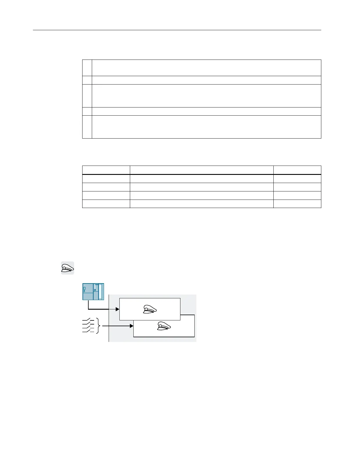
Overview
Several applications require the option of switching over the master control to operate the
converter.
Figure8-24 Converter control either via eldbus or via terminal strip
Function description
Command data set (CDS)
You can set the converter control in various ways and toggle between the settings.
The settings in the converter, which are assigned to a specic master control, are called the
command data set.
Advanced commissioning
8.12Switching over the drive control (command data set)
SINAMICS G120C Converters
Operating Instructions, 02/2023, FW V4.7 SP14, A5E34263257B AK 243
 Loading...


