Requirement
The U/f control or the vector control have been set.
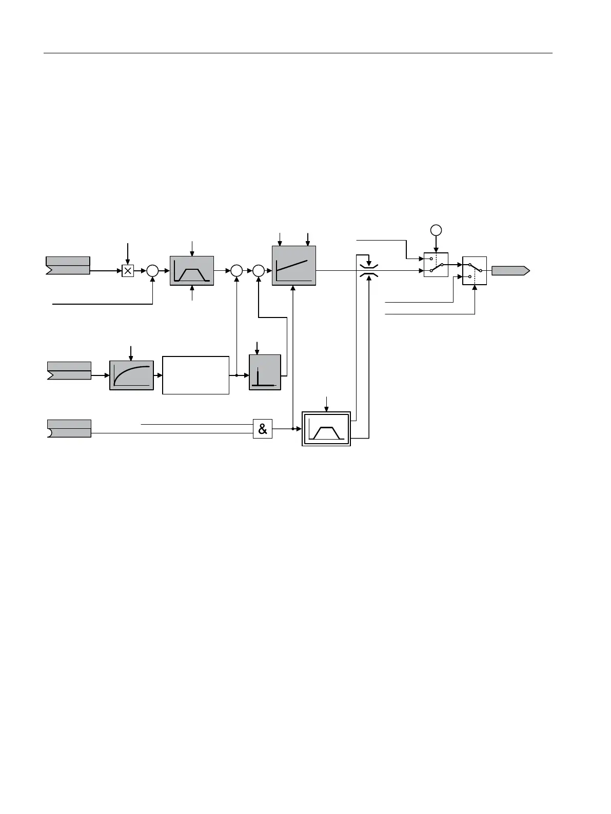
Function description
Function diagram
The technology controller is implemented as a PID controller (controller with proportional,
integral, and derivative action).
/LPLWDWLRQ
6FDOLQJ
,QYHUVLRQ
)XQFWLRQI[
2XWSXW
VLJQDO
6WDUWLQJYDOXH
5HVSRQVHWR
HUURUV
$FWXDOYDOXH
2XWSXWVLJQDOZLWK
HUURU
2SHUDWLRQLVHQDEOHG
WKHPRWRULVVZLWFKHGRQ
6PRRWKLQJ
3UHSDUDWLRQ
(QDEOH
&RQWUROOHU
HQDEOH
5DPSXSUDPS
GRZQWLPH
5DPSGRZQWLPH
5DPSXSWLPH
6HWSRLQW
6HWSRLQW
6FDOLQJ
U
S
S
S
S
S
S
S
S
S
.
3
7
G
7
,
① The converter uses the start value when all the following conditions are simultaneously satised:
• The technology controller supplies the main setpoint (p2251 = 0).
• The ramp-function generator output of the technology controller has not yet reached the start value.
Figure8-43 Simplied representation of the technology controller
Basic settings
The settings required as a minimum are marked in gray in the function diagram:
• Interconnect setpoint and actual values with signals of your choice
• Set ramp-function generator and controller parameters K
P
, T
I
and T
d
.
Advanced commissioning
8.19PID technology controller
SINAMICS G120C Converters
290 Operating Instructions, 02/2023, FW V4.7 SP14, A5E34263257B AK

 Loading...


