Connecting
6.9 Connection of a speed sensor
SIWAREX WT241
Manual, 05/2015, A5E36046748A 39
6.9 Connection of a speed sensor
If a speed sensor is connected to the WT241, this must always be made at digital input DI.0
of the module. This input is factory-configured for operation as a pulse counter. Check this
setting in data record 7 during commissioning.
The DI.0 can be found on the PCB board in the connection area ④.
Connection of the various Siemens speed sensors is shown below. A wide range of pulse
sensors can be used up to a clock frequency of 5 000 Hz. A level of at least +15 V DC is
required for the High signal. The Low signal is reached at a voltage of +5 V DC.
Detailed information on the various sensors can be obtained from the respective manual.
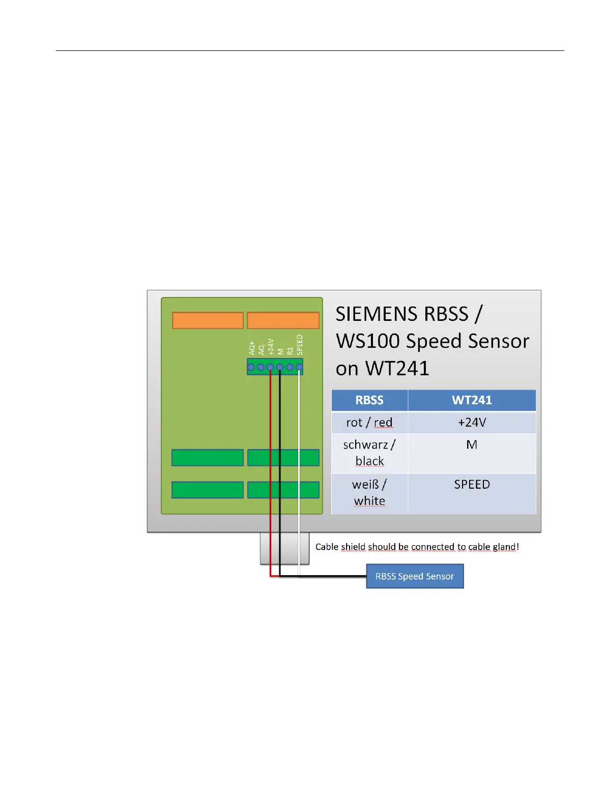
6.9.1 RBSS / WS100 speed sensor on WT241
Figure 6-11 RBSS speed sensor on WT241

 Loading...