EasyManua.ls Logo

Siemens Synco OZW772 Series User Manual

Siemens Synco OZW772 Series
176 pages
To Next Page IconTo Next Page
To Previous Page IconTo Previous Page
Page #102 background imageLoading...
Page #102 background image
102 / 176
Siemens Web server OZW772... V6.0 CE1C5701en
Building Technologies "Energy indicator" function 2015-10-12
The values of the data points "Energy indicator transmitted" and "Reason" are
displayed after testing until:
· Another test is triggered manually.
· The next transmitted e-mail is transmitted as per Transmit time 1 and/or 2.
· The device supply is switched on and off.
Data point Function
Test receiver [ ---, trigger]
"Energy indicator transmitted" [ ---, Yes, No]
Reason [ ---, DNS setting, mail server address, mail
server port number, e-mail address Receiver,
mail server authentication, network cable]
Manual triggering for test purposes does not trigger a fault message.
If an e-mail with "Energy indicator" of the plant is not transmitted without error,
a fault message is triggered for the corresponding e-mail Receiver.
The fault message is reset if:
· The next transmitted e-mail is transmitted as per Transmit time 1 and/or 2.
· Manually triggered "Test receiver" is successful.
The diagnostic options are identical to those of other e-mail Receivers.
7.5.2 Mail inbox
"Energy indicator
transmitted" and
"Reason"
Note
Fault message e-mail
Reset
fault message
Note

Table of Contents

Question and Answer IconNeed help?

Do you have a question about the Siemens Synco OZW772 Series and is the answer not in the manual?

Siemens Synco OZW772 Series Specifications

General IconGeneral
BrandSiemens
ModelSynco OZW772 Series
CategoryServer
LanguageEnglish

Summary

1 Overview

1.2 Web Server display and operating elements

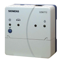
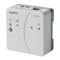
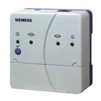
Details the physical components and indicators of the Web Server.

1.3 User interface

Explains the graphical interface and its main navigation areas.

2 Commissioning

2.1 Prerequisites

Outlines the necessary conditions before starting the commissioning process.

2.2 Getting started

Guides on initial setup and powering up the Web Server.

2.2.1 Turn on Web Server

Guides on how to power up the Web Server and initial checks.

2.2.2 Log into Web Server

Details the procedure for logging into the Web Server interface.

2.5 Web Server settings

Introduces the settings section for Web Server configuration.

2.5.3.3 Communication

Covers KNX communication settings, including device address and time sync.

Ethernet

Details Ethernet network configuration settings like DHCP, IP address, and DNS.

E-mail

Covers settings for sending emails, including address and authentication.

2.5.3.4 Message receivers

Describes how to configure message receivers for fault notifications.

2.5.3.9 Faults

Configures settings for sending fault notifications via email.

2.6 Commission network components

Explains how to connect and commission network components.

2.6.1 Access via portal

Explains how to access the Web Server via the Siemens Synco IC portal.

2.6.2 Access via a local area network (LAN)

Details how to access the Web Server via a local area network (LAN).

2.6.3 Access via direct connection

Explains how to establish a direct connection via the Internet.

2.7 Functional check

Guides on how to test the functionality of the Web Server and KNX devices.

2.9 Final steps

Details final checks and steps to complete the commissioning.

2.9.1 Check faults

Explains how to check for any pending faults before finalization.

2.9.2 Final steps on Web Server

Details final checks involving physical connections and LED status.

2.11 Software updates

Explains different types of software updates available for the Web Server.

3 Remote access via portal

3.1 Set up access via portal

Details the process of establishing remote access through the Siemens Synco IC portal.

4 Operate using a web browser

4.2 Operate the plant

Details how to operate the plant once it's ready for use.

4.2.1 Operate Synco device

Explains how to operate connected Synco devices via the Web Server.

4.2.2 Operate Web Server

Guides on operating the Web Server interface itself.

4.2.3 Web Server diagnostics

Shows how to access diagnostic information for the Web Server and KNX bus.

4.3 Faults

Provides an overview of the fault display and identification.

4.3.1 Overview

Provides an overview of the fault display and identification.

4.3.2 Device faults

Explains how to view detailed local faults for devices.

7 "Energy indicator" function

7.1.1 Function description

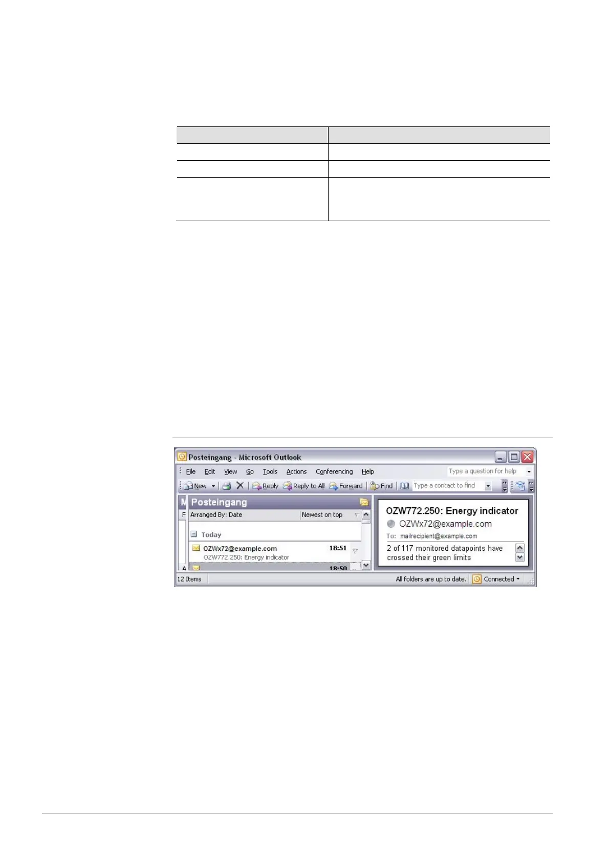
Explains how the Energy indicator works and its display logic.

7.3 "Energy indicator" commissioning function

Details the commissioning steps for the Energy indicator function.

7.3.4 Deactivating "Data point monitoring"

Describes how to deactivate data point monitoring for the Energy indicator.

7.3.5 Activating "Data point monitoring"

Explains how to reactivate data point monitoring for the Energy indicator.

7.4 Dialog boxes, data points, and "Green limits"

Explains how to work with dialog boxes, data points, and green limits.

8 Communications

8.1 Remote operation

Introduces methods for remotely operating the Web Server.

9 Trend functions

9.2 Define trend

Guides on defining trends through the web interface.

9.2.1 Define trend via web

Guides on defining trends through the web interface.

10 KNX S-Mode

10.1 Configuration in KNX S-Mode

Details the configuration process for KNX S-Mode using ETS.

Related product manuals