DCR-TRV725E/TRV730/TRV730E/TRV828/
TRV828E/TRV830/TRV830E
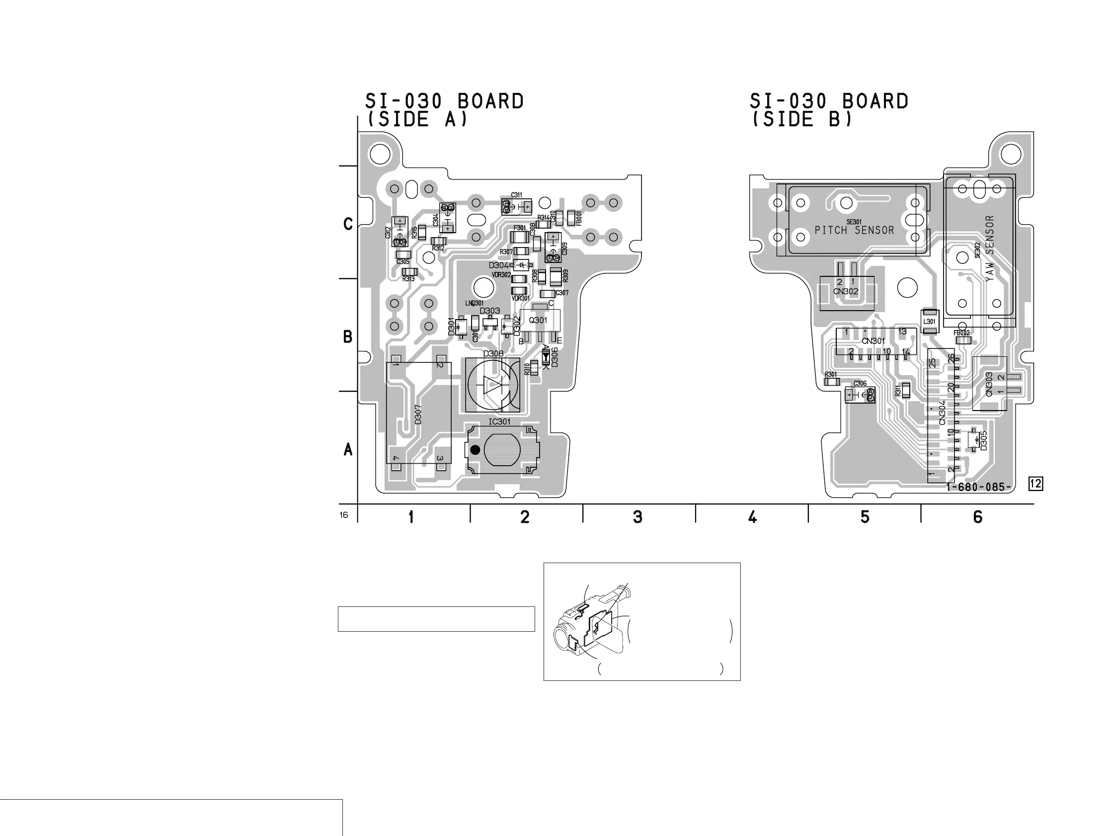
SI-030 (STEADY SHOT, REMOTE COMMANDER RECEIVER, LASER LINK) PRINTED WIRING BOARD
— Ref. No. SI-030 Board; 10,000 Series —
For printed wiring board
• Refer to page 4-106 for parts location.
• SI-030 board consists of multiple layers. However, only
the sides (layers) A and B are shown.
There are a few cases that the part printed on
this diagram isn’t mounted in this model.
STEADY SHOT, REMOTE COMMANDER RECEIVER, LASER LINK
SI-030
4-80
FP-315
(VTR FUNCTION SWITCH)
FP-283
(PANEL REVERSE)
SI-030
STEADY SHOT, REMOTE COMMANDER RECEIVER,
LASER LINK
VC-262
CAMERA PROCESS, LENS DRIVE,
JPEG/MPEG PROCESS, VIDEO PROCESS,
DV PROCESS, MODE CONTROL, SERVO,
AUDIO PROCESS, DC/DC CONVERTER
 Loading...