DCR-TRV725E/TRV730/TRV730E/TRV828/
TRV828E/TRV830/TRV830E
4-84
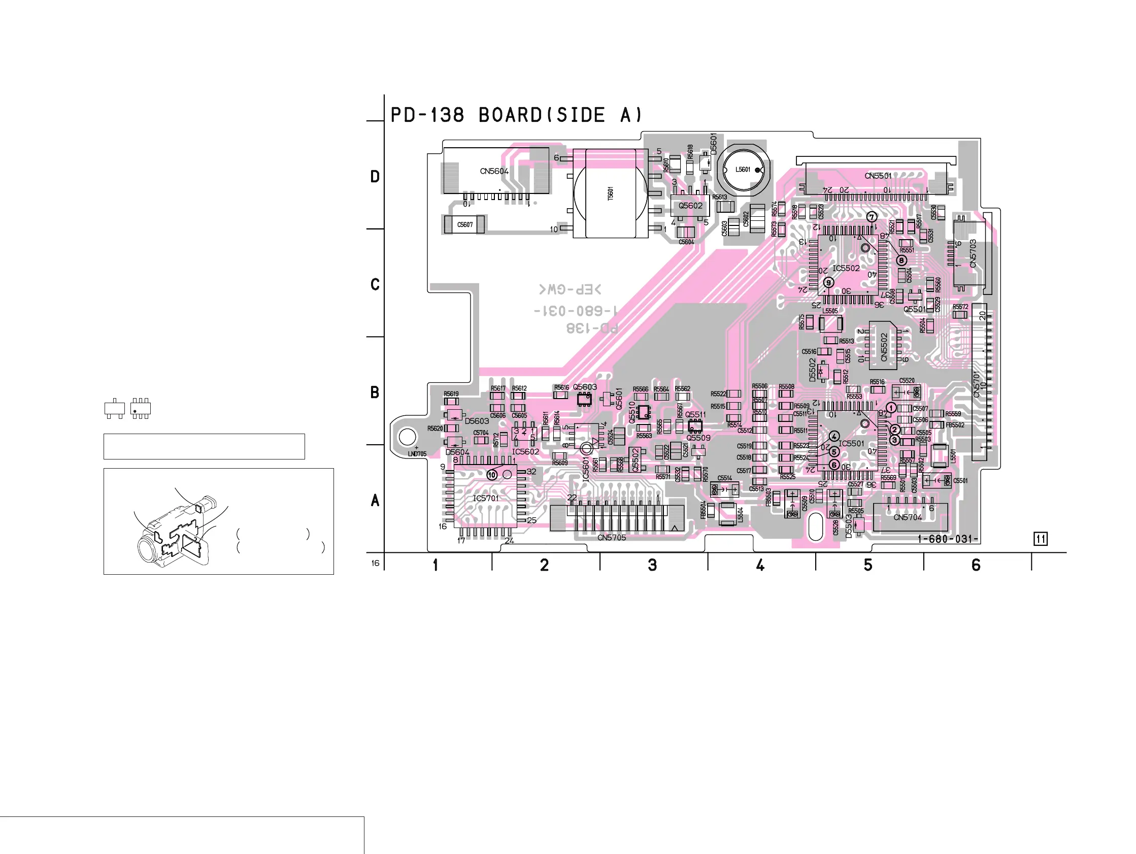
RGB DRIVE, TIMING GENERATOR, LCD DRIVE, BACK LIGHT DRIVE
PD-138
For printed wiring board
• Refer to page 4-106 for parts location.
• PD-138 board consists of multiple layers. However, only
the sides (layers) A and B are shown.
• Chip parts
Transistor
There are a few cases that the part printed on
this diagram isn’t mounted in this model.
C
BE
5
64
2
13
PD-138 (RGB DRIVE, TIMING GENERATOR, LCD DRIVE, BACK LIGHT DRIVE) PRINTED WIRING BOARD (DCR-TRV730)
— Ref. No. PD-138 Board; 10,000 Series —
CD-329
(CCD IMAGER)
LB-071
(EVF BACK LIGHT)
CF-084
(EVF DRIVE, USER FUNCTION)
PD-138 (TRV730)
PD-139 TRV725E/TRV730E/TRV828/
TRV828E/TRV830/TRV830E
RGB DRIVE, TIMING GENERATOR,
LCD DRIVE, BACK LIGHT DRIVE
 Loading...