2-3
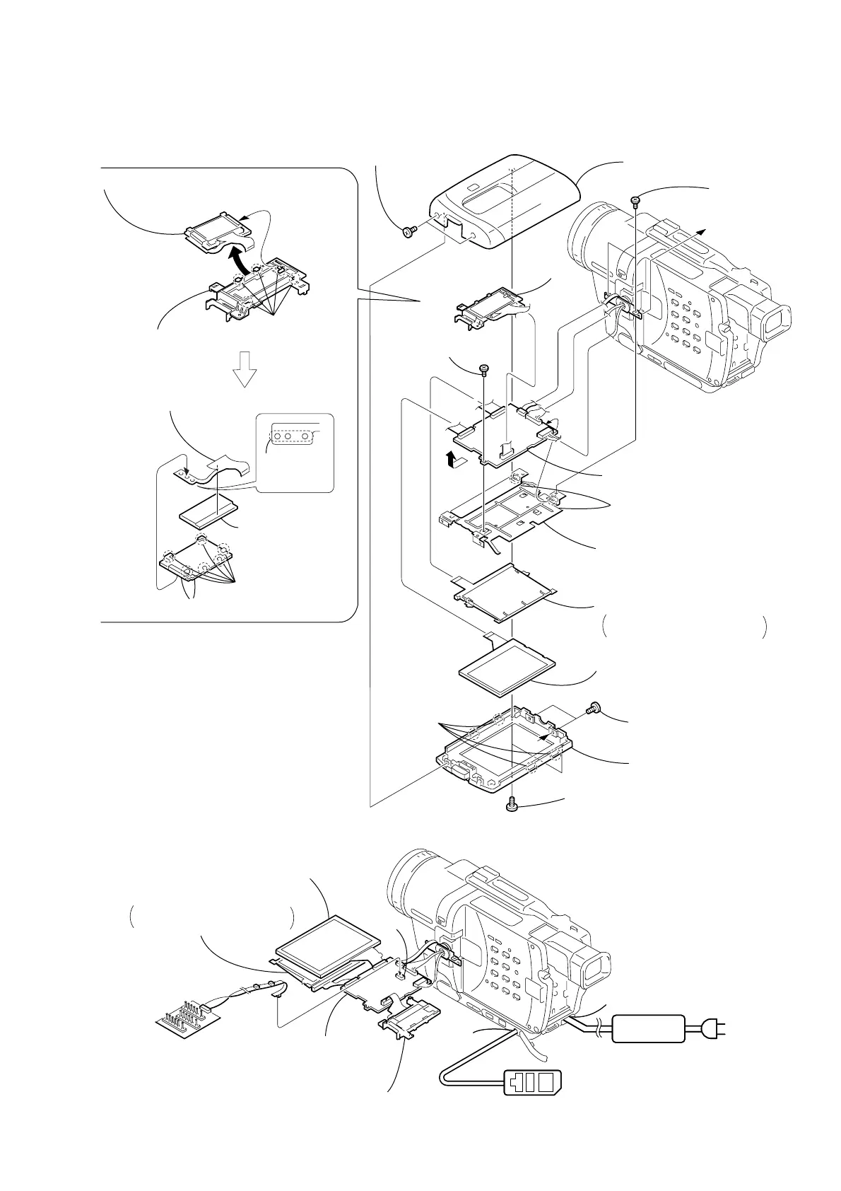
2-2. LCD UNIT, PD-139 BOARD (3.5 INCH LCD MODEL)
(TRV828/TRV828E/TRV830/TRV830E)
PD-139
Board
2
Two tapping screws
(M1.7
×
5)
1
Two MI screws
(M2
×
4) (H)
7
Two MI screws
(M2
×
4) (H)
6
Two screws
(M1.7
×
2.5), p
4
P cabinet C (M) assembly
8
P cabinet M (M3) assembly
[PD-139 BOARD SERVICE POSITION]
B
0
Two claws
3
Four claws
5
qd
Liquid crystal
indicator module
qa
Remove the PD-139 board in the
direction of the arrow
B
.
REMOVING THE BACK LIGHT
A
A
PD-139
Board
Adjustment remote
commander (RM-95)
PD-139 board
Liquid crystal indicator module
Indication LCD (M)
block assembly
AC IN
Back light
Cold cathode fluorescent tube,
BL shield sheet (N)
qf
Back light
Cold cathode fluorescent tube,
BL shield sheet (N)
LANC
jack
DC IN
AC POWER
ADAPTOR
CN5502
Multi CPC jig
(J-6082-311-A)
C
1
Five claws
3
LCD holder (M)
2
Remove the indication LCD (M) block assembly,
back light in the direction of the arrow
C
.
9
Screw
(M1.7
×
2.5), p
qs
P frame (M3),
PD electrostatic sheet (M)
LANC
jack
5
Six claws
6
FP-342 flexible
board (22P)
8
Back light
7
Liquid crystal
display panel
4
Remove
the three
solderings
 Loading...