5-46
3-3. SERVO AND RF SYSTEM ADJUSTMENT
Before perform the servo and RF system adjustments, check that
the specified value of “54/66MHz Origin Oscillation Adjustment”
of “VIDEO SYSTEM ADJUSTMENT” is satisfied.
Adjusting Procedure:
1. REEL FG adjustment
2. PLL fo & LPF fo pre-adjustment
3. Switching position adjustment
4. AGC center level and APC & AEQ adjustment
5. PLL fo & LPF fo fine adjustment
6. Hi8/Standrd8 switching position adjustment
7. CAP FG offset adjustment
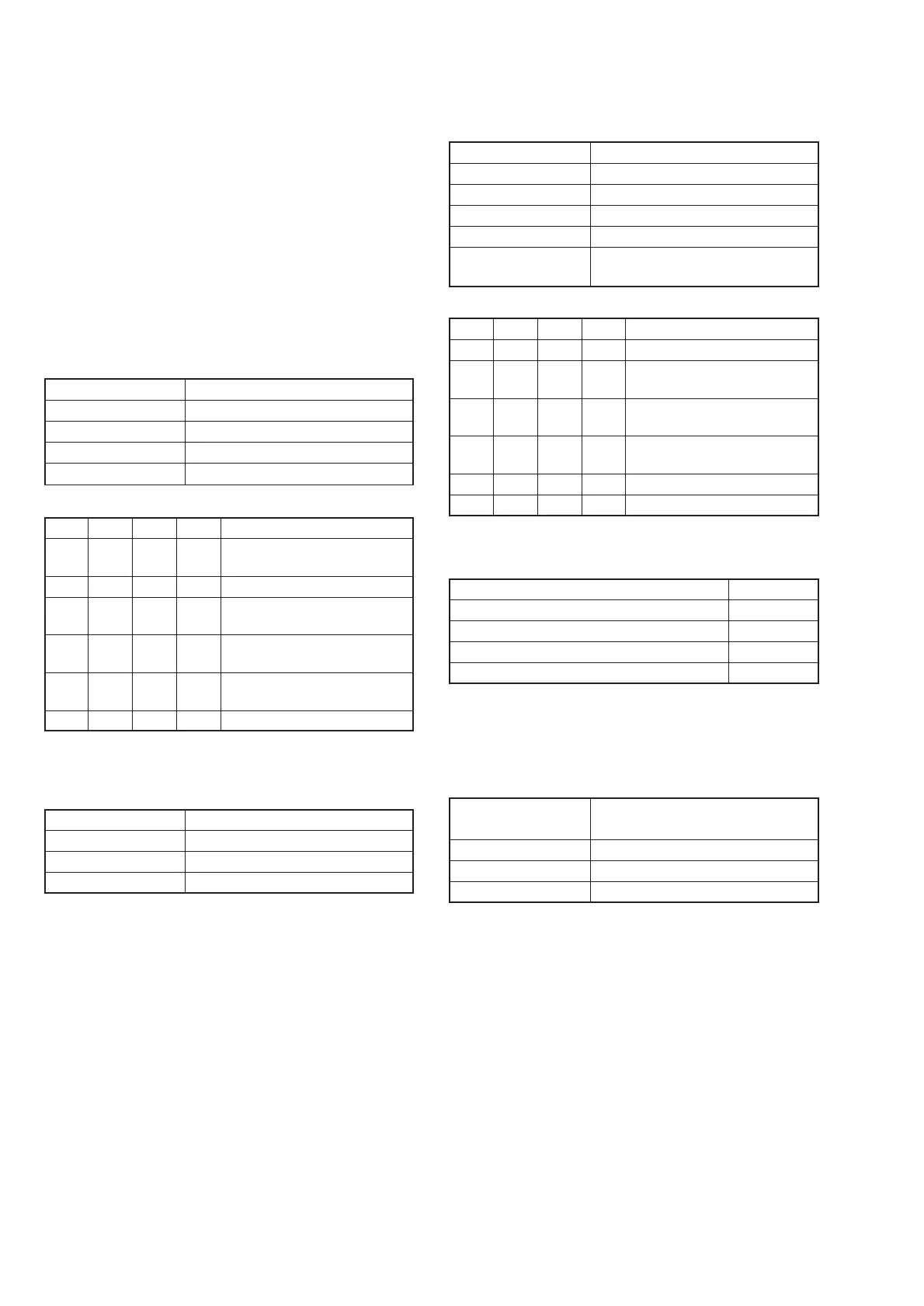
1. REEL FG Adjustment (VC-262 board)
Compensates the dispersion of the hall elements.
Measurement Point Display data of page: 3, address: 03
Measuring Instrument Adjustment remote commander
Adjustment Page C
Adjustment Address 17, 30
Specified Value 00 or 01 or 04 or 05
Adjusting method:
Order Page
Address
Data Procedure
1 Close the cassette compartment
without inserting a cassette.
2 0 01 01 Set the data.
3 3 01 1C Set the data, and press PAUSE
button.
4 3 02 Check that the data changes to
“00”,
5 3 03 Check that the data is “00” or
“01” or “04” or “05”. (Note)
6 0 01 00 Set the data.
Note: If the data is other value, adjustment has errors. (Take an appropriate
remedial measures according to the errors referring to the following
table.)
Data Contents of defect
02, 03, 06, 07 T reel is defective
08, 09, 0C, 0D S reel is defective
0A, 0B, 0E, 0F S reel and T reel are defective
2. PLL fo & LPF fo Pre-Adjustment (VC-262 board)
Mode VTR stop
Measurement Point Display data of page: 3
Measuring Instrument Adjustment remote commander
Adjustment Page C
Adjustment Address 1F, 20, 22, 29
Specified Value
The data of page: 3, address: 02 is “00”.
The data of page: 3, address: 03 is “00”
.
Adjusting method:
Order Page
Address
Data Procedure
1 0 01 01 Set the data.
2 3 01 00 Set the data, and press PAUSE
button.
3 3 01 30 Set the data, and press PAUSE
button.
4 3 02 Check that the data changes to
“00” within 10 sec. (Note)
5 3 03 Check that the data is “00”. (Note)
6 0 01 00 Set the data.
Note: If it isn’t satisfied, select page: C, address: 21, set the following
data, and press the PAUSE button, and repeat steps 2 to 5.
Setting data
When the data of page: C, address: 21 is “CA”. CE
When the data of page: C, address: 21 is “CE”. C6
When the data of page: C, address: 21 is “C6”. D2
When the data of page: C, address: 21 is “D2” C2
If bit2, bit3, bit4, bit5 or bit6 of page: 3, address: 03 data is “1”,
there are errors.
For the error contents, see the following table. (For the bit values,
refer to “5-4. SERVICE MODE”, “4-3. 3. Bit value discrimination”.)
Bit value of page: 3, Error contents
address: 03 data
bit 2 = 1 or bit 3 = 1 PLL fo fine adjustment is defective
bit 4 = 1 or bit 5 = 1 PLL fo adjustment is defective
bit 6 = 1 LPF fo is defective
RadarWRadarWRadarW
 Loading...