5-30
Pin No.
1
3
5
7
9
Signal Name
VB
VG
VR
XHD
GND
Pin No.
2
4
6
8
10
Signal Name
XVD OUT
PANEL COM/PSIG
MAKER CHECK
XHD OUT
GND
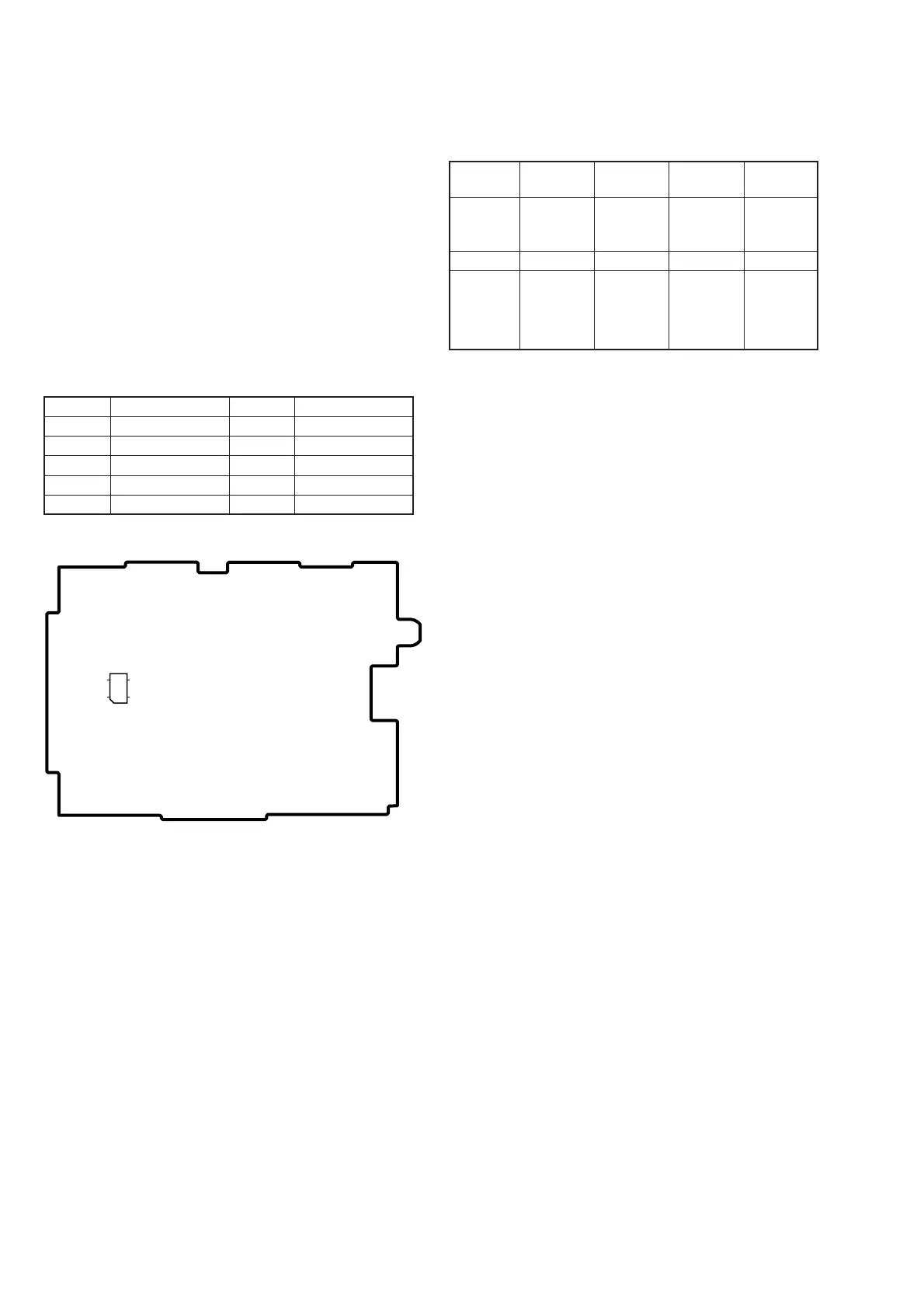
Fig. 5-1-15.
PD-138/139 board
CN5502
12
9
10
1-5. LCD SYSTEM ADJUSTMENT
Note 1: The back light (fluorescent tube) is driven by a high voltage AC
power supply. Therefore, do not touch the back light holder to
avoid electrical shock.
Note 2: When replacing the LCD unit, be careful to prevent damages
caused by static electricity.
Note 3: Set the LCD BRIGHT to the center.
Set the LCD COLOR (Menu display) to the center.
Note 4: PD-138 board: DCR-TRV730
PD-139 board:DCR-TRV725E/TRV730E/TRV828/TRV828E/
TRV830/TRV830E
[Adjusting connector]
Most of the measuring points for adjusting the LCD system are
concentrated in CN5502 of the PD-138/139 board. Connect the
measuring instruments via the multi CPC jig (J-6082-311-A). The
following table shows the Pin No. and signal name of CN5502.
Table 5-1-13.
[ LCD Type Check ]
By measuring the resistor value between Pin 6 of CN5502 and
GND, the type of LCD can be discriminated.
*1: Except AEP/UK model
*2: AEP/UK model
Table 5-1-14.
[Adjusting Procedure]
PD-138 board:
1. VCO adjustment
2. RGB AMP adjustment
3. Contrast adjustment
4. COM AMP adjustment
5. V-COM adjustment
6. White balance adjustment
PD-139 board:
1. VCO adjustment
2. PSIG gray adjustment
3. RGB AMP adjustment
4. Black limit adjustment
5. Contrast adjustment
6. Center level adjustment
7. V-COM adjustment
8. White balance adjustment
Resistor
value
LCD type
PD board
DCR-
1.0kΩ
2.5 LCD
TYPE SH
(61k)
PD-138
TRV730
22kΩ
2.5 LCD
TYPE SO
(61k)
PD-139
TRV730E(*1)
33kΩ
2.5 LCD
TYPE SO
(123k)
PD-139
TRV725E
TRV730E(*2)
47kΩ
3.5 LCD
TYPE SO
(123k)
PD-139
TRV828
TRV828E
TRV830
TRV830E
 Loading...