5-27
Pin No.
1
2
3
4
5
6
7
8
9
10
Signal Name
SWP
AFC F0
BPF MONI
FO ADJ RF IN
PB RF
REG GND
RF AGC OUT
VC RF SWP
COM DC
N.C.
Pin No.
11
12
13
14
15
16
17
18
19
20
Signal Name
VCO
EVF VG
DV RF SWP
RF IN
CAP FG
RF MON
TMS
TCK
TDO
TDI
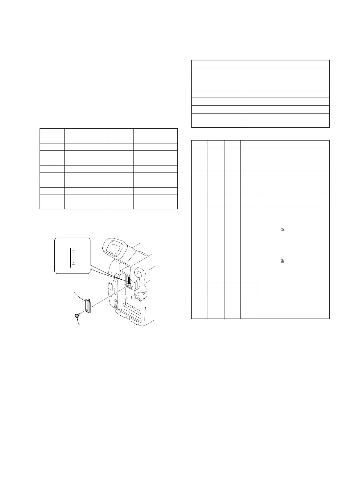
Fig. 5-1-12.
1-4. ELECTRONIC VIEWFINDER SYSTEM
ADJUSTMENT
Note1: When replacing the LCD unit, be careful to prevent damages
caused by static electricity.
Note2: Switch setting:
LCD panel ........................................................................... Close
[Adjusting connector]
Most of the measuring points for adjusting the viewfinder system
are concentrated in CN1108 of VC-262 board.
Connect the Measuring Instruments via the CPC-13 jig (J-6082-
443-A).
The following table shows the Pin No. and signal name of CN1108.
Table 5-1-12.
1. VCO Adjustment (CF-084 board)
Set the VCO free-run frequency. If deviated, the EVF screen will be
blurred.
Mode Camera
Subject Arbitrary
Measurement Point Pin qa of CN1108 of VC-262 board
(VCO)
Measuring Instrument Frequency counter
Adjustment Page D
Adjustment Address 92, 93
Specified Value f = 15734 ± 30Hz (NTSC)
f = 15625 ± 30Hz (PAL)
Adjusting method:
Order Page
Address
Data Procedure
1 0 01 01 Set the data.
2 D 92 Change the data and set the VCO
frequency (f) to the specified value.
3 D 92 Press PAUSE button.
4 D 92 Read the data, and this data is
named D92.
5 Convert D92 to decimal notation,
and obtain D92’. (Note)
6 Calculate D93’ using following
equations (Decimal calculation)
[NTSC model]
WhenD92’ 231
D93’=D92’+24
WhenD92’>231
D
93’=255
[PAL model]
WhenD92’ 24
D93’=D92’–24
WhenD92’<24
D93’=0
7 Convert D93’ to a hexadecimal
number, and obtain D93. (Note)
8 D 93 D93 Set the data, and press PAUSE
button.
9 0 01 00 Set the data.
Note: Refer to “Table 5-4-1. Hexadecimal-decimal Conversion Table”.
MI screw
(M2
×
4) (H)
Remove the
CPC lid (BT)
CN1108
20
1
 Loading...