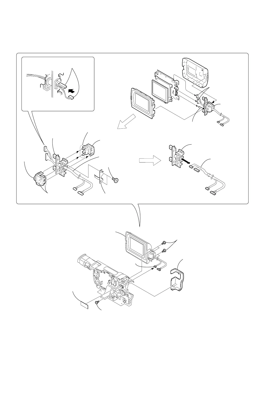
2-14
2-15.HINGE SECTION
CF-084
Board
5
Four tapping screws
(B2
×
5)
6
For removing the LCD unit
(See page 2-2, 2-3)
REMOVING THE HINGE ASSEMBLY
4
Hinge cover R (M)
3
Two tapping
screws (B2
×
5)
Remove the Harness (VP-076) (6, 20P)
in the direction of the arrow
A
.
Then bend the harness so that it is laid
along with the connector.
7
Hinge
assembly
2
Hinge
assembly
2
FP-283
board (6P)
2
FP-283 board
8
Harness (VP-076)
1
Harness
(VP-076)
(6, 20P)
1
Harness
(VP-076)
5
Hinge cover C (M)
1
Two screws
(M1.7
×
2.5), p
4
Two claws
6
Hinge
cover (M)
3
Four claws
2
Harness
(VP-076) (6P)
A
3
1
Tape (A)
 Loading...