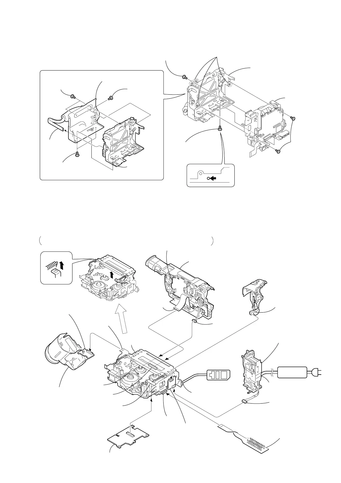
2-12.CABINET (L) SECTION, MECHANISM DECK-1
V
C
-262
Board
C
F
-084
B
o
ard
MM-043
Board
Adjustment remote
commander (RM-95)
LANC jack
CN1108
CN1104
CN1117
CPC-13 jig
(J-6082-443-A)
AC IN
DC IN
AC POWER
ADAPTOR
Control switch block
(SS-1380) (12P)
Battery panel
section
Battery terminal
board (6P)
[MECHANISM DECK SERVICE POSITION-1]
Note:
Use the parts only which can be removed easily from outside of the mechanism deck.
Operate the VTR using the adjustment remote commander. (with the HOLD switch set in the OFF position)
A
B
Remove the hook in the direction of the arrow
A
to raise the cassette compartment
in the direction of the arrow
B
.
FU-155 board
MM-043 board
CN1120
SI-030 board
Front panel
section
Cabinet (R) block
assembly
Flexible flat cable
(FFC-001) (45P)
Harness
(VP-076)
(20P)
CF-084 board
4
Four dowels
5
Cabinet (L) section,
CS frame assembly (M)
1
Two screws
(M1.7
×
2.5), p
3
Screw
(M1.7
×
2.5), p
2
Screw
(M1.7
×
2.5), p
5
Cabinet (L)
assembly
1
MI screw
(M2
×
4) (H)
3
Two MI screws
(M2
×
4) (H)
2
Two MI screws
(M2
×
4) (H)
4
Grip
belt (ES)
REMOVING THE CS FRAME ASSEMBLY (M)
6
CS frame
assembly (M)
6
How to raise the cassette compartment manually
Mechanism deck
FP-316 flexible
board (26P)
 Loading...