HT-ST9
14
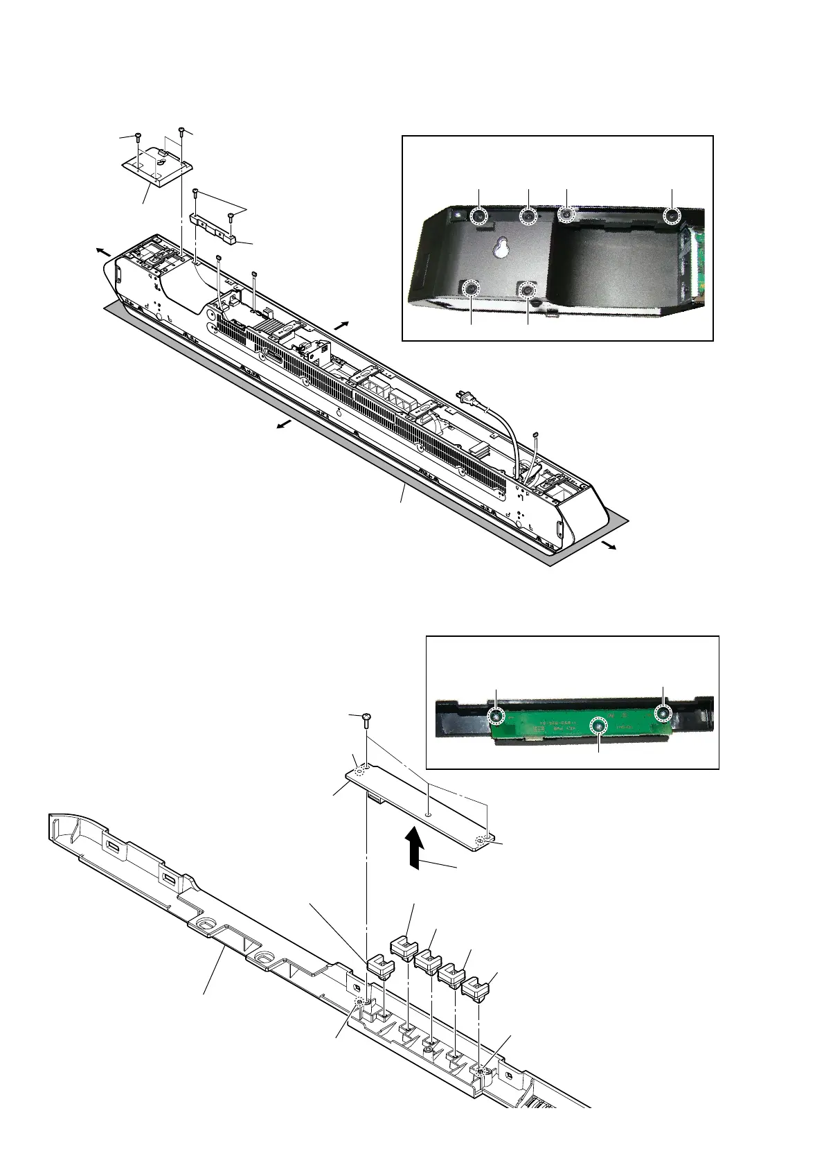
2-4. REAR PANEL (R) ASSY, BASE COVER (REAR)
2-5. KEY BOARD, BUTTON ASSY
– Rear view –
Note 1:
Lay a soft piece of cloth
under the unit to avoid
damaging the grille assy.
4 two screws
(BVTP3 u 8)
5 base cover (rear)
2 two screws
(BVTP3 u 8)
1 two step
screws
(B3 u 6)
3 rear panel (R) assy
Right side
Top side
Left side
Bottom side
Note 2:
When installing screws, follow the installing procedure
in the numerical order given.
1
6 5
234
– Cover (rear) block front bottom view –
1 three screws
(BVTP2.6)
2
1
3
2
Remove the KEY board
in the direction of the arrow.
4
button (VOL) assy
5
button (rear) assy
5
button (rear) assy
5
button (rear) assy
5
button (rear) assy
Note 1:
When installing screws, follow the installing
procedure in the numerical order given.
cover (rear) assy
hole
3 KEY board
Note 2:
When installing the KEY board,
align the two guide pins and two
holes.
guide pin
guide pin
hole
 Loading...