HT-ST9
34
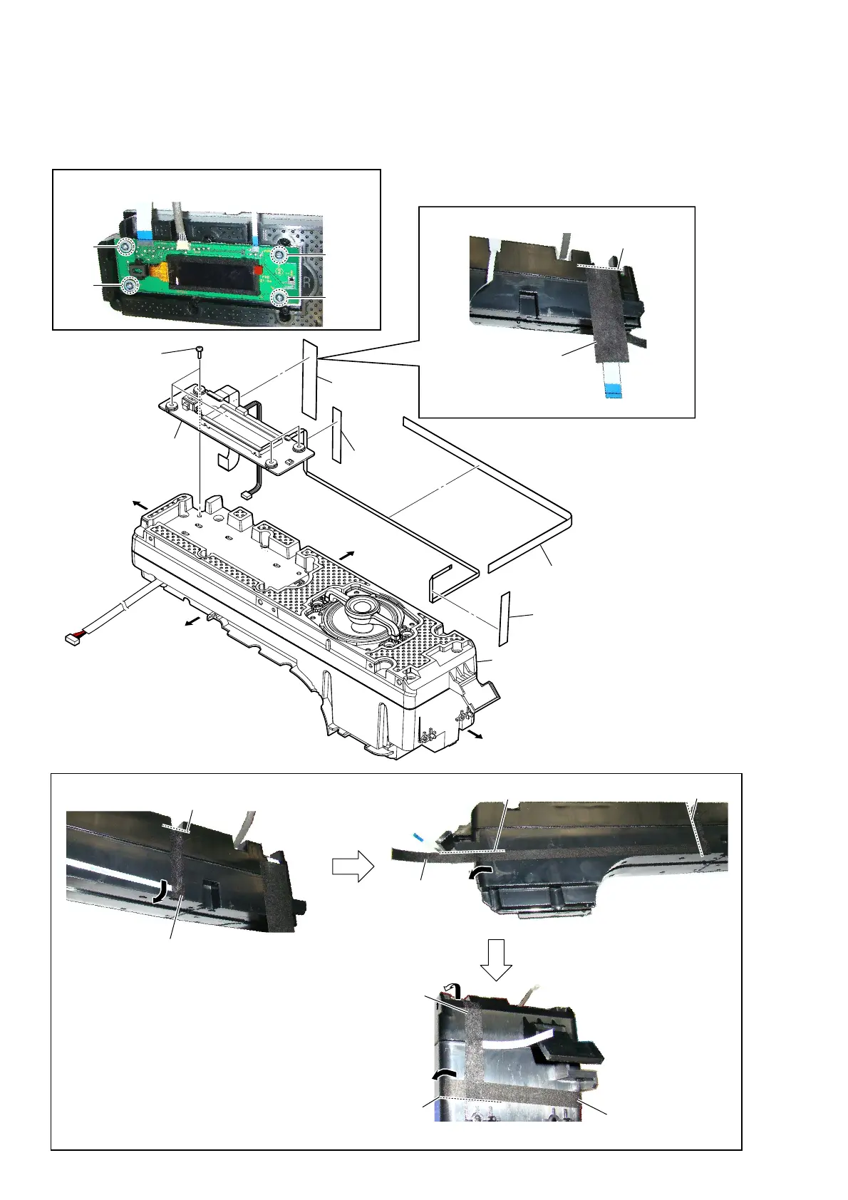
2-26. DISPLAY BOARD BLOCK-1
• Continued on 2-27 (page 35).
– Speaker (R-ch) block front view –
1 saranet cushion
guide line
2 cushion (wire NFC)
3 saranet
cushion
6 DISPLAY board block
4 cushion
(wire DISP)
5 four screws
(BVTP3 u 12)
cushion
(wire DISP)
,nVtallation poVition of the cXVhion (wire ',S3)
– Speaker (R-ch) block top view –
guide line
– Speaker (R-ch) block right view –
guide line
guide line
saranet cushion
cushion
(wire NFC)
saranet
cushion
guide line
cushion
(wire NFC)
– Speaker (R-ch) block top view –
– Speaker (R-ch) block top view –
Right side
Top side
Left side
Bottom side
speaker (R-ch) block
1
2
3
4
Note:
When installing screws (BVTP3 × 12), follow the installing
procedure in the numerical order given.
+ow to inVtall the Varanet cXVhion anG cXVhion (wire 1)&)
 Loading...