HT-ST9
22
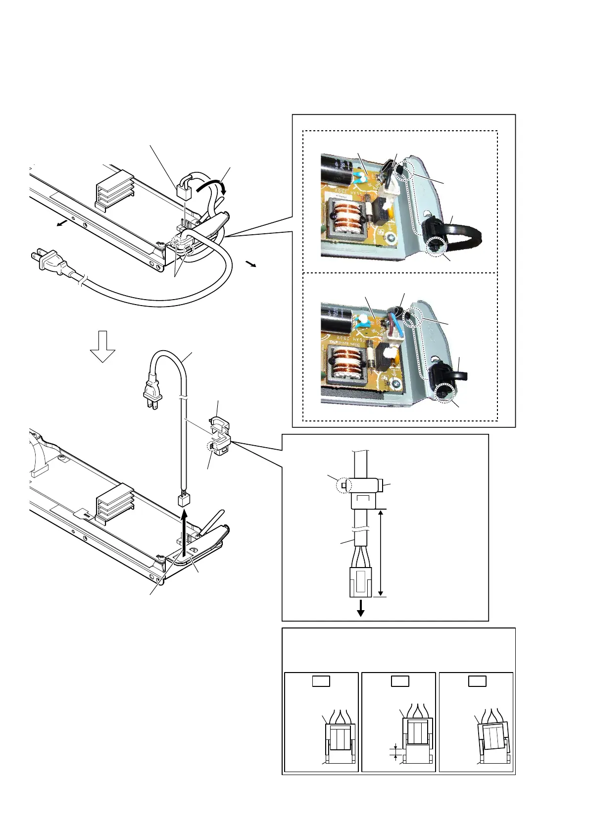
2-13. POWER CORD (AC1)
power cord
(AC1)
cord bushing
(FBS001)
claw
150 +5, -0 mm
to POWER board
– Chassis block rear view –
2 power cord connector
(CN901)
1 Remove the power cord
from the wiring stopper.
5 claw
7 power cord (AC1)
3 two claws
4 Draw the power cord block out
of the hole in chassis assy.
6 cord bushing
(FBS001)
3RZHUFRUG$&VHWWLQJ
claw
groove
wiring stopper
–&KDVVLVEORFNWRSYLHZ–
power board
hole
power cord
(AC1)
Bottom side
Left side
Insert only part way.Insert straight into
the interior.
connector
Insert at a slant.
connector
connector
connector
connector
connector
OK NG NG
+RZWRLQVWDOOWKHFRQQHFWRU
Insert the connector straight into the interior.
There is a possibility that using this unit without
the connector correctly installed will damage it.
86&1'
claw
groove
wiring stopper
–&KDVVLVEORFNWRSYLHZ–
power board
power cord
(AC1)
([FHSW86&1'
,QVWDOODWLRQSRVLWLRQRIWKHFRUGEXVKLQJ)%6
 Loading...