HT-ST9
16
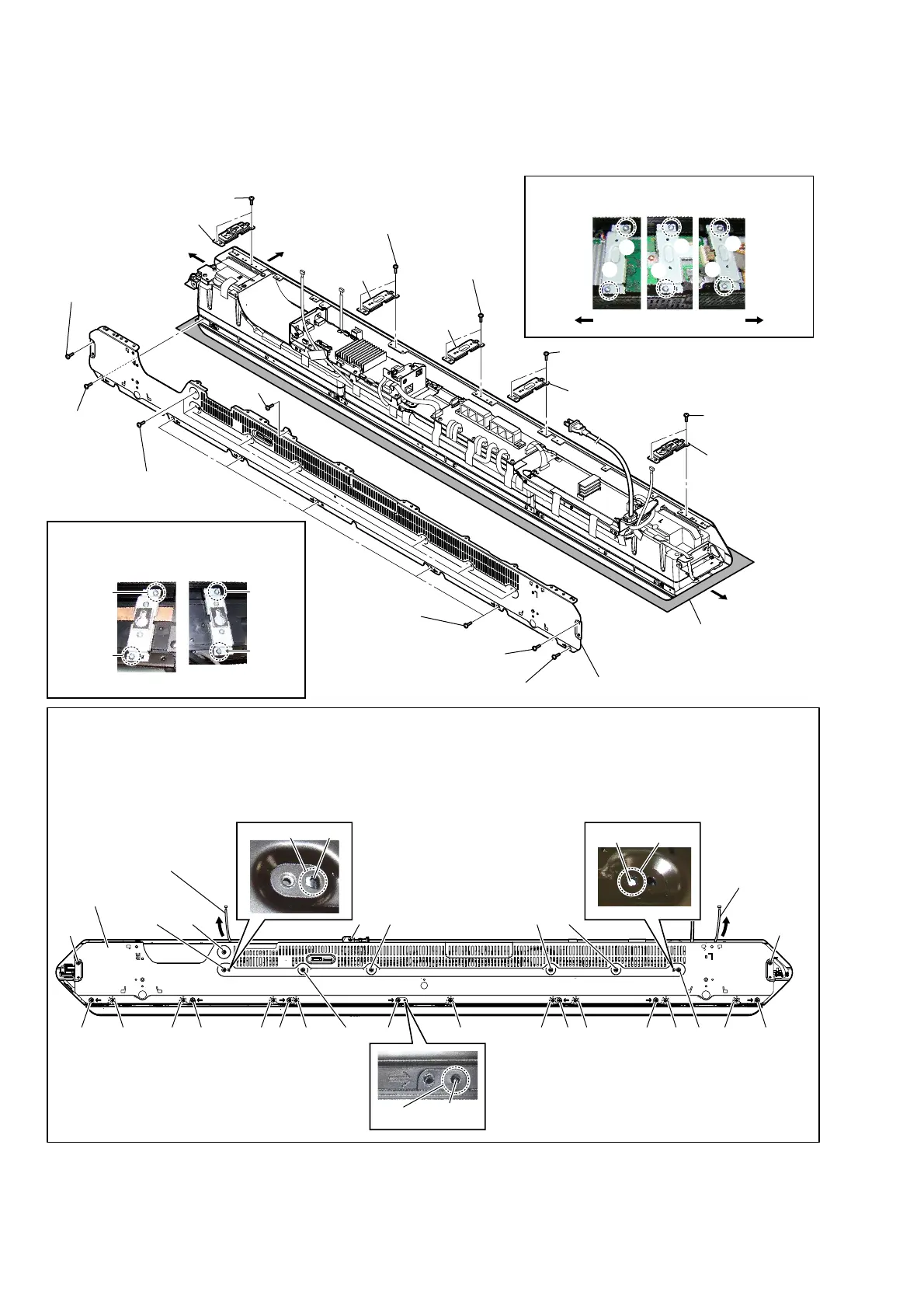
2-7. PANEL (BOTTOM) BLOCK
5 screw
(BV/ring)
5 screw
(BV/ring)
5 seven screws
(BV/ring)
5 screw
(BV/ring)
5 screw
(BV/ring)
5 five screws
(BV/ring)
5 screw
(BV/ring)
6
panel (bottom) block
– Rear view –
Note 1:
Lay a soft piece of cloth
under the unit to avoid
damaging the grille assy.
1RWHVZKHQDVVHPEOLQJRUGLVDVVHPEOLQJWKHSDQHOERWWRPEORFN
–%RWWRPYLHZ–
rib
guide pin
rib
hole
hole
hole
panel (bottom) block
ŸŸŸ ŸŸŸŸŸŸ
Right side
Right side
Top side
Left side
Left side
Disassembling:
Removing the nine screws at the
Ÿ
mark screws is not necessary.
Assembling:
Align the guide pin and two ribs with three holes, and then fasten with seventeen screws at the numerical order (
1
to
qj
) given.
Draw out the REPEATER_REP1 board cable and REPEATER_REP2 board cable before installation.
1
5
6
7
2
3
8
9
0
qg
qh
qj
qa
qs
qd
qf
4
REPEATER_REP1
board cable
REPEATER_REP2
board cable
1 two screws
(BVTP3 u 8)
1 two screws
(BVTP3 u 8)
1 two screws
(BVTP3 u 8)
3 two screws
(BVTP3 u 8)
3 two screws
(BVTP3 u 8)
2
bracket
(arm)
2
bracket
(arm)
2
bracket
(arm)
4
bracket (wall)
assy
4
bracket (wall) assy
Note 2:
For the bracket (wall) assy, install the
screws in the numerical order given in
the figure below.
13
4
2
Right side Left side
Note 3:
For the bracket (arm), install the screws in the
numerical order given in the figure below.
1
3
5
6
4
2
 Loading...