HT-ST9
27
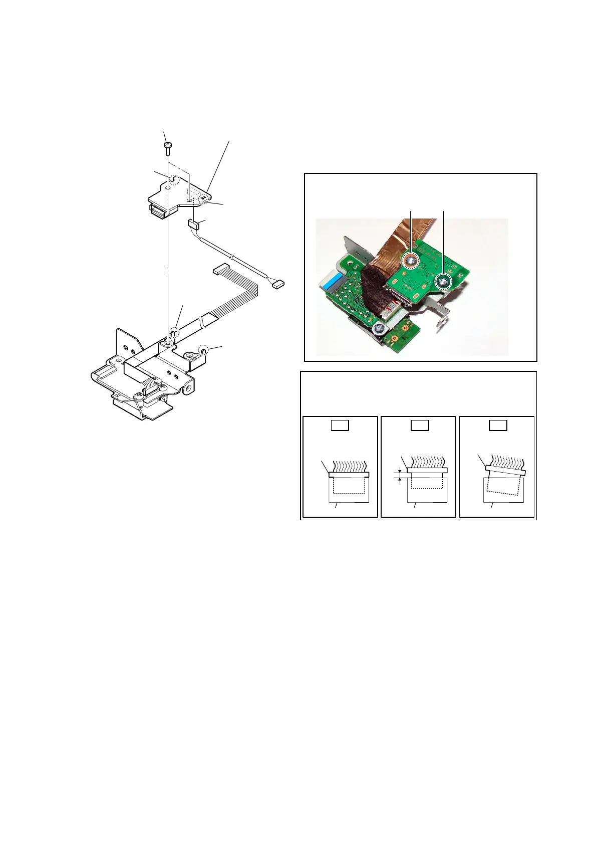
2-18. USB BOARD
– RF modulator block rear bottom view –
2 two screws
(BVTP3 u 8)
1 connector
(CN1501)
Insert only part way.Insert straight into
the interior.
connector
Insert at a slant.
connector
connector
connector
connector connector
OK NG NG
How to install the connector
Insert the connector straight into the interior.
There is a possibility that using this unit without
the connector correctly installed will damage it.
guide pin
guide pin
hole
groove
3 USB board
Note 1:
When installing the USB board,
align the hole and groove with
the two guide pins.
Note 2:
When installing screws (BVTP3 × 8), follow the installing
procedure in the numerical order given.
21
 Loading...